Installation and Maintenance Manual - Aastra 5000
AMT/PTD/PBX/0058/4/6/EN
Description des sous-ensembles
01/2011
Page
133
Indicators
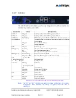
The ADS 350X power supplies include 6 indicators on the front panel giving the following
indications:
4.2.3.5
Hardware configuration
The mains voltage, 115 V or 230V (+/- 10%), is detected automatically, internally.
4.2.3.6
Installation and wiring
The ADS 350X power supply module is supplied with a battery connection cable fitted
with a 4 pin connector, with a centring piece to prevent polarity inversion when connecting
the backup battery.
SYMBOL
INDICATOR STATE
EXPLANATION
On
Line Power Present
On
Battery connected
On
Rectifier On
On
Converter On
On
Bell current generator On
On
Fans present
On
40 V ISDN present
TABLEAU 4.3 PRESENTATION OF ADS 350X POWER SUPPLY
MODULE INDICATORS
48V
40 V
IS
Summary of Contents for AXD
Page 16: ...AMT PTD PBX 0058 4 6 EN Installation and Maintenance Manual Aastra 5000 Page 16 01 2011...
Page 20: ...AMT PTD PBX 0058 4 6 EN Installation and Maintenance Manual Aastra 5000 Page 20 01 2011...
Page 22: ...AMT PTD PBX 0058 4 6 EN Installation and Maintenance Manual Aastra 5000 Page 22 01 2011...
Page 26: ...AMT PTD PBX 0058 4 6 EN Installation and Maintenance Manual Aastra 5000 Page 26 01 2011...


