background image

C

ORDLESS

 P

HONE

38

6/1531-ANF 901 14 Uen F1 2013-11-29

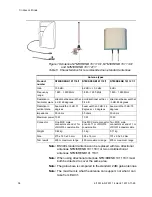
The antenna set NTM/KRENB 101 119/1 contains the following items:

Antenna

Wall mounting bracket

Pole mounting clamp

Two antennas must always be connected to one base station, both 
covering the same area.
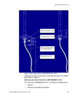
The antenna can be mounted on a wall or on a 25 to 37 mm diameter 
tube. When mounted on a vertical wall the supplied wall mounting 
bracket should be used, the bracket can be used both turned upwards 
and downwards. Screws to fasten the bracket on the wall has to be 
purchased locally. Two Ø 4 mm screws are needed. When mounted on 
a tube, both the supplied wall mounting bracket and the pole mounting 
clamp should be used. The wall mounting bracket has to be turned 
downwards. Please see figure 19 Mounting antenna NTM/KRENB 101 
119/1 on page 39 for details.
Tests have shown that for antenna NTM/KRENB101 119/1 a distance of 
50 cm between the antennas is recommended, this to avoid the shad-
owing effect.

Summary of Contents for CORDLESS PHONE

Page 1: ...INSTALLATION INSTRUCTION INSTALLATION INSTRUCTION 6 1531 ANF 901 14 F1 2013 11 29 Cordless Phone Mattias Wenzel mwenzel Tero Silvennoinen...

Page 2: ...LU31 3 refers to ROF 137 5412 3 and ELU31 4 refers to ROF 137 5412 4 If not mentioned specifically ELU31 refers to ELU31 3 and ELU31 4 all boards are assumed to have latest FW co operability is only g...

Page 3: ...chronization source Accuracy on the delay values are critical ACDM shall be used to auto matic calculate the delay values on the synchronization ring The customer installation will be covered by a num...

Page 4: ...mmand CXCFC rngpri yes Server 1 mgw 1A mgw 1B mgw 1C mgw 2A mgw 2B mgw 2C mgw 2D Base station Base station Base station Base station Base station Base station Base station Server 3 lbp 22 mag 0 mag 1...

Page 5: ...rt of comprehensive guidelines and established permitted levels of RF energy for the general population These guidelines are based on the safety standards previously set by both US and international s...

Page 6: ...e FCC has granted an equipment authorization for the DT69x DT630 and DT4x3 with all reported SAR levels evaluated as in compliance with the FCC RF emission guidelines RF Exposure The internal external...

Page 7: ...tion instructions for INSTALLING MX ONE Installation instructions for UPGRADING OF PORTABLES Command descriptions for BOARD CONFIGURATION Installation Guide Base Station 3 Preparations 3 1 Upgrading o...

Page 8: ...oaded to the RFP 3 3 General preparations Installation planning shall be completed see the installation planning for CORDLESS PHONE but pay special attention to the considerations described below Do a...

Page 9: ...on the 2 084 kbit s hierarchy ITU T Recommendation G 824 or equivalent ETSI EN 302 084 The control of jitter and wander within digital networks which are based on the 1 544 kbit s hierarchy Note ETSI...

Page 10: ...tribute synchronization to media gateways PCM timing can be distributed to all media gateways with the DECT synchronization ring See chapter 3 4 3 Introduction to the synchro nization ring on page 13...

Page 11: ...l be the source of the PCM timing for all Media Gateways having ELU31 Ring Members The PDRM will become Ring Master as long as the DECT Ring is intact 2 The PDRM must never provide PCM timing towards...

Page 12: ..._4_mode to enable the clock diagnostics reporting If redundant synchronization mechanism is required a second PRI link is connected to a second PRI and designated as secondary synchroni zation source...

Page 13: ...d via a synchronization ring structure The ring consists of several logical interfaces Due to timing requirements it is important that all wire pairs follow the same path Can not be divided to differe...

Page 14: ...ation roles will not start connect base stations A remote gateway can be its own RING MASTER and have a separate synchronization ring connect TX to RX It shall have PCM synchroniza tion source free ru...

Page 15: ...is not needed between the boards when there is no radio coverage between them server 1 server 2 mgw 2B mgw 2A mgw 1B mgw 1A Ring Synchronization cabling Base station Base station Base station Coverag...

Page 16: ...ample of a star configuration on page 16 and figure 7 Example of a ring configuration on page 17 The ring configuration is only recom mended when the distance in the star configuration will exceed the...

Page 17: ...inted by the ring negotiation This new Ring Master will stop providing PCM clock to its MGU In stead the Holdover function of this MGU oscillator will guarantee a continuous and stable PCM timing that...

Page 18: ...not used as possible synchro nization source media gateway ELU31 4 MGU x PSTN media gateway ELU31 4 MGU x media gateway ELU31 4 MGU 2 E1 media gateway ELU31 4 MGU x or optionally PCM PCM PCM free runn...

Page 19: ...alcu lated by the ACDM The RING MEMBERS may be given a delay value see the commands CXCFI and CXCFC in the command description for CORDLESS media gateway ELU31 4 MGU x PSTN media gateway ELU31 4 MGU x...

Page 20: ...for compensating for this delay ACDM does this measurement automatically to validate the result can two methods be used The typical delay across a 1 km copper cable is 5 35 micro seconds approx 40 st...

Page 21: ...han 50 ns It must be possible to measure the delay across the distance covered by the media 4 Unpacking 4 1 ELU31 board 4 1 1 Measures Ensure that the correct product has been delivered Remove the ant...

Page 22: ...n this section should be used as a reference Regarding slicing and bundle of the pairs in the cable between the ELU31 board and MDF MDM see document Installing MX ONE instal lation instruction At the...

Page 23: ...as described earlier see chapter 7 2 Cable requirements on page 51 The base stations are connected to the ELU31 board via MDF or MDM Two or three pairs are needed where two pairs SC0 SC1 are for signa...

Page 24: ...asure the voltage at the base station This should be done when 8 calls are active at the same base station The voltage should comply with the requirements see chapter 9 3 1 Base stations on page 57 Ta...

Page 25: ...6 1531 ANF 901 14 Uen F1 2013 11 29 25 MOUNTING INSTALLATION 5 5 Front connector ELU31 twisted pair cable Figure 10 ELU31 board front connections...

Page 26: ...SCO Base stn 6 SC1 SCO Base stn 7 SC1 SCO Base stn 0 SC1 SCO Base stn 1 SC1 SCO Base stn 2 SC1 SCO Base stn 3 SC1 1 2 3 4 5 6 7 9 0 8 EPP Base EPP Base EPP Base EPP Base EPP Base EPP Base EPP Base EPP...

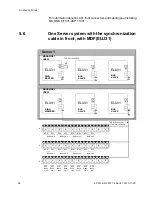
Page 27: ...1 29 27 MOUNTING INSTALLATION Figure 11 One Server system with the synchronization cable in front and Main Distribution Frame MDF 19 ASB 501 04 The LBP22 backplane consists of both magazine 0 and 1 so...

Page 28: ...stn 5 SC1 SCO Base stn 6 SC1 SCO Base stn 7 SC1 SCO Base stn 0 SC1 SCO Base stn 1 SC1 SCO Base stn 2 SC1 SCO Base stn 3 SC1 1 2 3 4 5 6 7 9 0 8 EPP Base EPP Base EPP Base EPP Base EPP Base EPP Base EP...

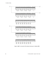
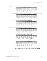
Page 29: ...ions 07 ASB 501 04 or 09 ASB 501 04 ELU31 ELU31 ELU31 ELU31 ELU31 ELU31 TX RX TX RX TX RX TX RX TX RX TX RX Server 1 MAGAZINE 1 Server 2 LBP22 MAGAZINE 1 LBP22 BUS SLAVE BUS SLAVE BUS SLAVE BUS SLAVE...

Page 30: ...stn 3 stn 4 stn 5 stn 6 stn 7 SCO Base stn 12 SC1 SCO Base stn 13 SC1 SCO Base stn 14 SC1 SCO Base stn 15 SC1 SCO Base stn 8 SC1 SCO Base stn 9 SC1 SCO Base stn 10 SC1 SCO Base stn 11 SC1 1 2 3 4 5 6...

Page 31: ...13 SC1 SCO Base stn 14 SC1 SCO Base stn 15 SC1 SCO Base stn 8 SC1 SCO Base stn 9 SC1 SCO Base stn 10 SC1 SCO Base stn 11 SC1 1 2 3 4 5 6 7 9 0 8 EPP Base EPP Base EPP Base EPP Base EPP Base EPP Base E...

Page 32: ...figure 16 Connections when using 2 EPP pairs on page 34 and chapter 6 2 Dimensioning on page 46 Software If necessary the software in the base station can be updated by down loading new software to t...

Page 33: ...r cable may be used when additional power wires EPP are required to increase the distance between the base station and the ELU31 The base station is connected to the local MDF via a terminal box NEF 1...

Page 34: ...l or a pole outside of buildings see chapter 5 11 Outdoor housing SDC 905 04 1 for base stations on page 41 Note The BS34x base station cannot be mounted with the antennas pointing downwards as the mo...

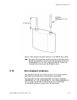
Page 35: ...116 The X rings SCGNB 101 104 that are included in the antenna set should not be used 5 10 Non standard antennas Non standard antennas are not fixed directly onto the base station s MCX antenna connec...

Page 36: ...101 118 1 NTM KRENB101 119 1 NTM KRENB 101 121 1 Gain 10 5 dBi 6 2 dBi 0 3 dBi 8 dBi Frequency range 1 880 1 920 MHz 1 880 1 930 MHz 1 850 1 990 MHz Radiation in horizontal plane directional beam wid...

Page 37: ...with minimum loss Outdoor connections must be made water tight by using self vulca nizing rubber tape Next use electrical tape to block out direct sunlight on the vulcanizing tape Lightning protectio...

Page 38: ...ll mounting bracket should be used the bracket can be used both turned upwards and downwards Screws to fasten the bracket on the wall has to be purchased locally Two 4 mm screws are needed When mounte...

Page 39: ...antenna NTM KRENB 101 119 1 For BS340 see figure 17 Mounting the standard antennas on the BS340 base station on page 35 Mounting instructions for antenna NTM KRENB 101 121 1 The antenna set NTM KRENB...

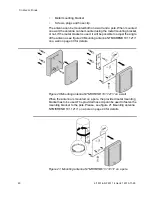
Page 40: ...le to adjust the angle of the antenna see figure 20 Mounting antenna NTM KRENB 101 121 1 on a wall on page 40 for details Figure 20 Mounting antenna NTM KRENB 101 121 1 on a wall When the antenna is m...

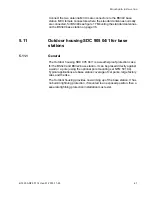
Page 41: ...1 for base stations 5 11 1 General The Outdoor housing SDC 905 04 1 is a weatherproof protection case for the BS3x0 and BS3x2 base station It can be placed directly against a wall or a pole using the...

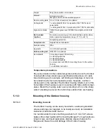
Page 42: ...g The mounting plate is drilled 2 times and two wooden screws for mounting the base station BS3x0 3x2 are mounted to the plate 5 11 2 Specifications for the Outdoor housing Physical Specifications sub...

Page 43: ...matching washers for 6 mm 1 4 screws between the screw heads and the mounting flanges For rough walls use longer screws and insert appropriate distance sleeves between the flanges and the wall to avo...

Page 44: ...ertion of the data cable and the other for the connection cable to external antennas 5 11 4 1 Cabling for the BS3x0 and BS3x2 These base stations are powered via the data power cable from for example...

Page 45: ...d to the Data Power outlet RJ45 or to the connection box NEF 181 01 4 5 11 6 Post mounting measures When the Outdoor housing is mounted in place with the connected base station and the connection box...

Page 46: ...13 Installation of charging equipment 5 13 1 DT390 DT690 and DT692 See direction for use Configuration manual DT390 69X 5 13 2 DT413 DT423 and DT433 See direction for use Configuration manual DT4x3 6...

Page 47: ...ation Figure 24 Connections when using 2 EPP pairs Maximum power available from one ELU31 board in an LBP22 maga zine or later with two 48 V pins in the backplane is 109 W 42 x 1 3 x 2 Using the backp...

Page 48: ...4 board Maximum 5 0 W Typical 2 8 W BS3x2 Maximum 2 0 W Typical 1 3 W BS330 base station R4H and later figures without cable length Maximum 2 0 W Typical 1 3 W BS340 base station R4H and later figure...

Page 49: ...etween MDF or MDM for base station connection and for synchronization must also follow these recommendations see chapter 7 2 Cable requirements on page 51 Two types of front cabling are used on the EL...

Page 50: ...tions when using 2 EPP pairs on page 47 Care should also be exercised not to short circuit the wires or swap polarity At the initial time when the system is installed and the ring is connected for th...

Page 51: ...les between ELU31 board and base stations on page 23 It is good practise to avoid laying the above mentioned cables close to other cables carrying high currents and high frequencies Examples of cables...

Page 52: ...e connected from the SYNC TX port to the SYNC RX port on the same ELU31 board Note When ELU31 board are used in the ring the mentioned cables must be used 7 4 Base station cable Cable TSR 910 1054 can...

Page 53: ...station cable ELU31 8 Post installation measures See section 10 Appendix B on page 58 See installation instructions for INSTALLING MX ONE Any front plates and other cabinet plates that have been remo...

Page 54: ...6 d mm A BS340 base station measures 200 w x 252 h x 56 d mm with standard antenna For space requirements for non standard antennas see Table 5 Characteristics for recommended non standard antennas on...

Page 55: ...can be higher ELU31 3 FW R7B and greater and ELU31 4 has improved ring commu nication and ACDM function Therefor is it recommended to use these board in the ring ELU31 4 has an on board switch The swi...

Page 56: ...1 versions with some limita tions See 5 1531 ANF 901 14 section 2 ELU31 4 index 3 mode and ELU31 3 FW R7B can coexist on the ring 9 2 2 Base stations 9 2 2 1 BS3x2 and later base stations See document...

Page 57: ...base stations See document Installation Guide Base Station 9 3 1 2 BS330 NTM KRCNB 301 03 1 with GAP SW for frequencies between 1880 1900 MHz and NTM KRCNB 301 02 1 with GAP SW for frequen cies betwee...

Page 58: ...Appendix B 10 1 Installation test instruction 10 1 1 General The mobility installation is tested by walk around test that is walking a predetermined way while making call and receiving call and walki...

Page 59: ...ange Check that the number of system the phone is registered to are correct See Direction for Use Cordless phones Normally only one Having only one working site and having more then one registration c...

Page 60: ...all ELU31 boards are inserted and initiated the synchronization ring should complete and the ELU31 boards should have a defined role Following steps needs to be checked controlled executed All compone...

Page 61: ...RX inlet As long as there is one single fault in the ring no board will respond properly Note If RING MASTER is missing in the printout but the other boards have indication of RING MEMBER or BUS SLAV...

Page 62: ...none Parity as none Data bits as 8 Stop bits 1 and select the DTR enabled and RTS enabled under Control signal Now press OK Then click Open Now a new window will open If enter key is pressed ELU31 pr...

Page 63: ...diagnostic_print request get alarm logs or get sw alarm logs the alarm logs can be cleared with request clear alarm logs 10 1 5 6 Test of radio coverage To be able to carry out a careful test of the r...

Page 64: ...continuously ON due to traffic making it almost impossible to use the method above This second less reliable method is to scan through all the PARI numbers and check their signal strength SS The PARI...

Page 65: ...Repeat the action with a terminal in speech to check the hand over behavior In addition Range beep and Error rate beep could be used to sort out possible weak areas Verify that the test result corres...

Page 66: ...DT690 menu and press Yes Select Call time and press Yes Scroll right then press Scroll left twice then press Scroll left Admin menu appears The DT690 is now in service mode To use DCA service during s...

Page 67: ...key 1 This displays some variables used when roaming and doing hand over The values indicated are Press and hold key 2 This displays PARK for the subscriptions For more than one subscription press the...

Page 68: ...e same type used on site Fill in the data Alternative is to take a picture of the map with the point marked and another picture of the two displays Table 14 Measuring point data Table 15 Enter data ab...

Page 69: ...6 1531 ANF 901 14 Uen F1 2013 11 29 69 APPENDIX B Figure 29 Marked position on the map Figure 30 Measuring data...

Reviews: