background image

Page 120

01/2007

 AMT/PTD/PBX/0020/2/4/EN

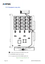
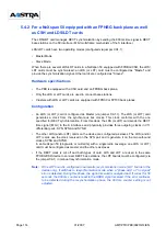
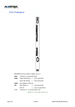
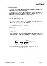
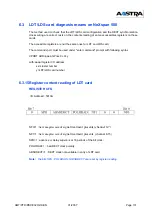
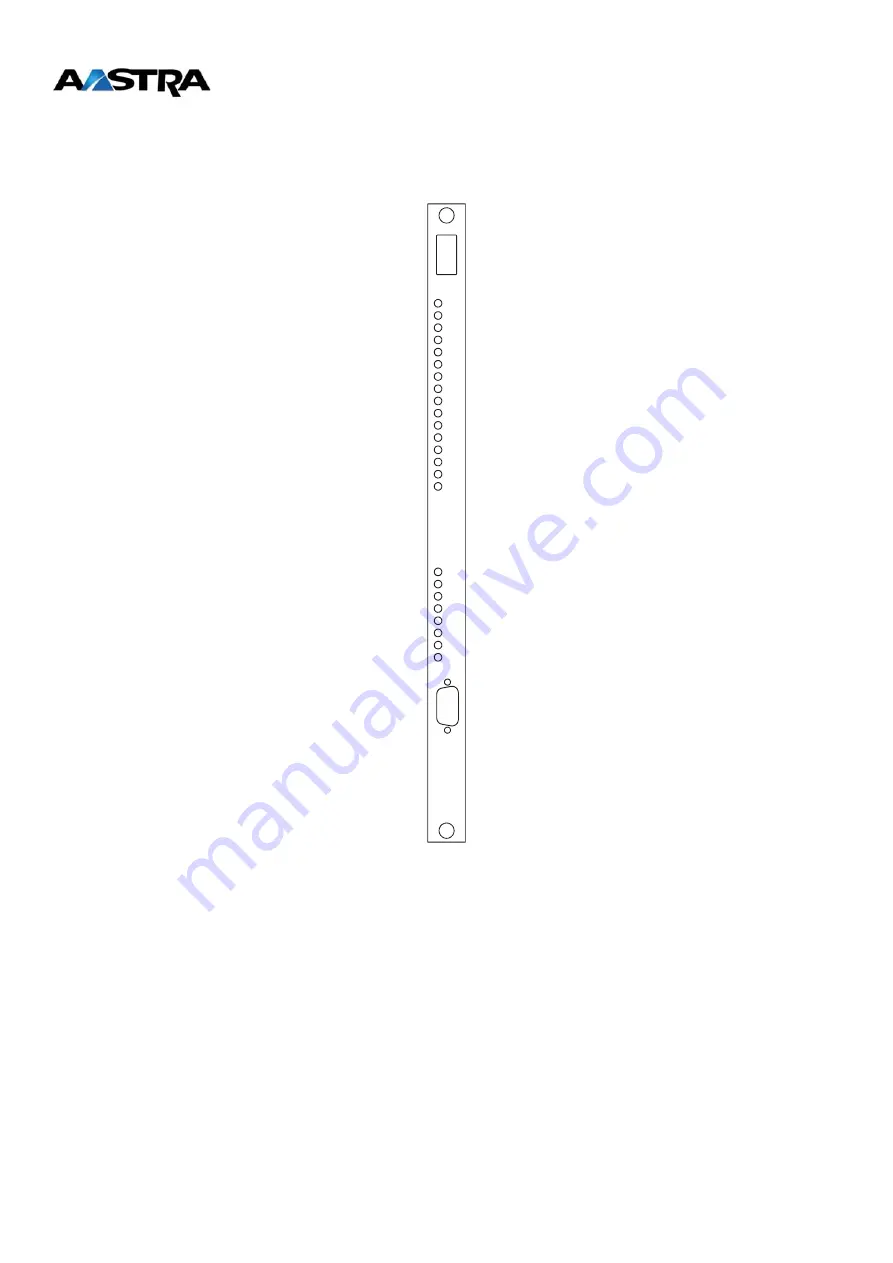
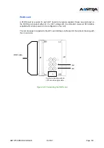
6.2.2 Front panel

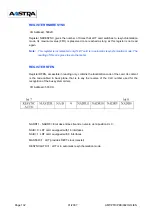
S0 to S15 

Interface Activation Display (level 1)

ANR

      Address not recognised (Fault)

REA5

     Rapid LED flashing  --> Card operational

Slow LED flashing  --> Card operational

REA6

     Not significant (LED off)

PM


LED steady on

--> Card operational

LED off

--> Card not operational

+ 5 V


Presence of + 5 V powering the card

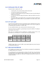
Figure 6-1: Front panel of LDT card


S0 

ANR 

REA5 

REA6 

PM 

+ 5 V


S15


T


J3 

Summary of Contents for NeXspan C

Page 1: ...Integrated DECT Service Installation guide NeXspan C S L D NeXspan 50 NeXspan 500 AMT PTD PBX 0020 2 4 EN 01 2007 AASTRA MATRA Telecom...

Page 2: ...Page 2 01 2007 AMT PTD PBX 0020 2 4 EN...

Page 3: ...ation of the old M6241 DECT base station 31 2 2 5 Configuration of the new M6241 DECT base station 32 2 3 M90x mobile terminals 33 2 3 1 Physical description of an M90x mobile 33 2 3 2 Configuring an...

Page 4: ...RJ45 connectors 74 4 4 2 Switch settings 75 4 4 3 Position of LD4 RJ card 76 4 4 4 Connecting base stations 76 4 5 Factory configuration of the LD4NX ST card with Stocko format 78 4 5 1 Description o...

Page 5: ...5 3 5 LDT card layout 107 5 3 6 Connecting the LDT board 108 5 3 7 Distribution frame wiring with cable HG4302A 110 5 3 8 Distribution frame wiring with cable HG4302B 111 5 4 synchronization 112 5 4...

Page 6: ...136 7 3 Synchronization on M6501 L R RM IP PBX and Succession 6500 Media Gateway with OCT4 OCT4 I 140 7 3 1 Principles of installation 140 7 3 2 Wiring of synchronization ports 141 7 4 synchronization...

Page 7: ...cards in service 168 9 5 Declaring and putting in service DECT base stations 170 9 5 1 Declaring and defining a base station 170 9 6 Checking the programming 172 9 6 1 Display the base stations 172 9...

Page 8: ...guration 187 11 1 1 Contiguous multi site configuration 187 11 1 2 Non contiguous multi site configuration 188 11 2 Declaring the radio zones on NeXspan 50 NeXspan 500 188 11 3 Programming the DECT pa...

Page 9: ...t principles This chapter describes the deployment method for a given installation i e definition of the radio coverage the number of base stations and the dimensioning of the system Chapter 4 Impleme...

Page 10: ...ce for NeXspan C S L D Chapter 10 Programming for the NeXspan 50 NeXspan 500 range This chapter describes the programming steps to put in service the integrated DECT service for NeXspan 50 and NeXspan...

Page 11: ...ating manual NeXspan C S L D Volume 1 AMT PTD PBX 0046 5 Operating manual NeXspan C S L D Volume 2 AMT PTD PBX 0052 6 Operating manual NeXspan C S L D Volume 3 AMT PTD PBX 0053 7 Installation manual C...

Page 12: ...Xspan 500 F6 PBX range comprising NeXspan D XD NeXspan L XL NeXspan S XS and NeXspan C XC FPS Fixed Part Subnumber GAP Generic Access Profile IPEI International Portable Equipment Identity IPUI Intern...

Page 13: ...is in free space spherical and centered on the base station A base station must belong to a trunk group in the MMCs Overlapping base stations Base stations with the same radio coverage 3 base station...

Page 14: ...h other They constitute a single radio area B4 and B5 are base stations each with its own radio area Each time a cordless handset is located at the intersection of these three areas it recognises the...

Page 15: ...low 3DH while the CRC is still at 40H the limit of the radio area is reached Example Radio area centre Location of a base station or antenna serving a radio area Radio range The distance between the r...

Page 16: ...zontal and vertical axes This overlap is required so the roaming and handover phases take place in good radio conditions During deployment you must measure the significant values CRC RSSI of the radio...

Page 17: ...section point These conditions allow you to ensure quality of service for roaming and handover Case of theoretical limits Case of two base stations without handover RSSI Hex 60 Bx base station studied...

Page 18: ...lation Code distributor reference example AASTRA managed by the ETSI FPN FPS Fixed Part Number and Fixed Part Sub number Network user reference AASTRA customer or PBX reference see below managed by AA...

Page 19: ...bile has access to the entire multi site network Each PBX has the same PARI s Multi site base station access is by a common SARI Access authorization is performed by testing the PARK registered in the...

Page 20: ...Page 20 01 2007 AMT PTD PBX 0020 2 4 EN...

Page 21: ...nna diversity a feature that ensures optimal reception quality within the coverage area The number of radio base stations used depends on the size of the coverage area and the level of traffic support...

Page 22: ...d on any F4 and F6 device The new base station is physically identical to the old M6241 base station Only obsolete components of the electronic card are replaced Table 1 DECT base station references S...

Page 23: ...tations according to PBX type see the corresponding section on Deployment principles and Implementation of hardware Rules for spacing cables relative to interference sources 1 high interference indust...

Page 24: ...the support feed the cable through the indented upper part of the base station designed for this purpose Note the DECT base station is a restricted access device Installation and maintenance must only...

Page 25: ...pins are used for connection to the S0 Basic Rate Interface pins 3 to 6 2 pins are used for connection to the synchronization signal pins 1 and 2 for synchronization by 3rd pair Note The RSx pair car...

Page 26: ...ly The base station is powered from the PBX The remote current supplied on the S0 interface card is limited to 100 mA which corresponds to an available supply of 4 W at 40 V or 48 V The base station c...

Page 27: ...this antenna do not add cables between the antenna and the base station The radiating element therefore has to be placed in immediate proximity of the base station Conversely a remote connection must...

Page 28: ...enna extension lead The maximum length of the extension lead is approximately 2 8 meters This extension lead ensures identical performance of the Internal antenna and External antenna configurations w...

Page 29: ...n a repeater must be used to connect the slave base stations to the master base station The master base station must be the base station closest to the distribution frame It is strongly recommended to...

Page 30: ...idirectional Integrated or external antennas Coverage range from 10 to 30 meters in an office environment and up to 300 meters in an open air environment Base station operating temperature 5 45 C Numb...

Page 31: ...The base station reset is only activated when the base station or PBX power is on CA1 2 on OFF The base station reset is controlled by level 1 of the S0 interface factory configuration Switches S202 S...

Page 32: ...on resistor on the synchronization pair factory configuration CA1 2 on ON The base station reset is only activated when the base station or PBX power is on CA1 2 on OFF The base station reset is contr...

Page 33: ...r more detailed information refer to document 3 see Reference documents on page 11 Specifications Weight 135 grams Dimensions 135 x 58 x 19 mm Autonomy 10 hours talktime 100 hours in standby mode GAP...

Page 34: ...under paragraph B If the mobile displays it is already registered on at least one other base 1 Press the Menu key 2 Press the middle key until Select base is displayed 3 Press the Select base key Any...

Page 35: ...displayed 3 Press the Personalize key 4 Press the middle key or several times until Declare is displayed 5 Press the Declare key The display shows 6 Press the or key to select the base to be deleted...

Page 36: ...mode To check the base station range radio areas To check that the handover function is working correctly To check that the clock wiring is correct To check EMC and radio interference When to use DEB...

Page 37: ...handover in cell XX C2C2 R2R2 RPN and RSSI Indicates second best available base station for handover in cell XX C2C2 R2R2 Indicates that on the next page there are more than 3 base stations in cell XX...

Page 38: ...4 RPN and RSSI Indicates the fourth best available base station for handover in cell XX C5C5 R5R5 RPN and RSSI of all the other base stations seen by the mobile in different cells C6C6 R6R6 RPN and RS...

Page 39: ...minal Description The M910 M915 mobile terminal comprises a terminal a charging unit an adapter 3 AAA NiMH batteries 2 User Guides in French and English Figure 2 9 View of an M910 mobile terminal For...

Page 40: ...rench German Spanish Italian Dutch Norwegian Swedish and Portuguese M915 Specifications Weight 150 grams Dimensions 135 x 51 x 29 mm Autonomy 10 hours talktime 100 hours in standby mode Registration o...

Page 41: ...AMT PTD PBX 0020 2 4 EN 01 2007 Page 41 Headset for M915 Specifications Plug diameter 2 5mm 32 ohms mini headset reference TC2070A Figure 2 10 View of an M915 mobile terminal...

Page 42: ...n choose the base station compared to the name seized into 5 Note After registering the mobile terminal to change the PBX name and or the Int No use the selection Menu Device OK Save OK Opt Edit enter...

Page 43: ...s of the mobile terminal and its ID Master Reset for cancelling the mobile s one and only basic subscription Pin reset used to cancel the mobile s internal information and restore the factory configur...

Page 44: ...raphical display extended directory search and call by name inbound call log outbound call log Additional features quick memories ringer off shortcut masking of the Declare menu mobile terminal access...

Page 45: ...t 10 numbers called Call locking pre numbering and automatic off hook Integrated directory supporting 100 alphanumerical entries Volume amplification volume control Power 0 25 Watts RSSI characteristi...

Page 46: ...inciple is to associate an extended directory memory to each key on the keypad 1 to 9 To quickly start a call from any of these memories just press and hold down the corresponding key until the associ...

Page 47: ...d on at least one other base 1 Press the Menu key 2 Press the middle key until Select base is displayed 3 Press the Select base key Any base numbers already in use are displayed These numbers must be...

Page 48: ...y shows 5 Press the or key to select the base to be deleted and confirm by pressing the OK key The set displays n base number Press the key yes The set displays 6 Press the OK key without entering cod...

Page 49: ...interference When to use DEBUG mode The user complains of Breaks in communication Incorrect operation of the handover function Crackling during a communication Line seizure with UNAVAILABLE The displ...

Page 50: ...ounter in alarm mode C1C1 R1R1 RPN and RSSI Indicates best available base station for handover in cell XX C2C2 R2R2 RPN and RSSI Indicates second best available base station for handover in cell XX C2...

Page 51: ...tation for handover in cell XX C4C4 R4R4 RPN and RSSI Indicates the fourth best available base station for handover in cell XX C5C5 R5R5 RPN and RSSI of all the other base stations seen by the mobile...

Page 52: ...e RFPI Radio Fixed Part Identity is 40 bits information for example 10 06 F0 FF 4A The first 4 bytes give the device s PARI and the last byte the RPN Radio fixed Part Number The RFPIs of the detected...

Page 53: ...ed the mobile possesses the PARK y information item containing the first y significant bits of the ARI PARI or SARI used to encode the right of access This information is loaded into the mobile when i...

Page 54: ...e mobile sends a request to the base station for a transfer If the response is positive the mobile remains synchronized on the base station and continues analysing the signalling control channel It is...

Page 55: ...Stocko or RJ45 ADPCM16 48 V supplied by ADS300X 40 base stations 4 channels NeXspan S XS LD4 LD4NX Stocko or RJ45 ADPCM16 48 V supplied by ADS100X 8 base stations 4 channels UCT1 S 48 V supplied by AD...

Page 56: ...NeXspan 50 NeXspan 500 The maximum number of DECT mobile terminals is 256 for one CCU PBX S0 interface cards Power Capacity For 1 CCUs LDS ADPCM32 or LDT ADPCM32B 48 V supplied by ADS850 64 base stati...

Page 57: ...tomer In this step gather all the information necessary to determine the coverage areas and the traffic for each area 2 Determining and segmenting the radio coverage area The overall coverage area mus...

Page 58: ...rea covered by each base station Problem areas can also be identified and documented The coverage tool kit can then be used to check the locations indicated on the map and taking into account the traf...

Page 59: ...ote the differences in respect to the typical radio area size 3 Measure the radio area size on a horizontal plane from the middle floor 4 To measure the radio area size make a call using a mobile and...

Page 60: ...the one mapped In particular check the coverage in problematic areas such as near elevators staircases and the ends of building If there are poor coverage areas try to locate the base stations elsewh...

Page 61: ...otal number of mobile DECT users Z number of radio areas in the traffic area m the mobility of users within a given traffic area Mobility is defined for each user based on information provided by the...

Page 62: ...omogeneous area Z Number of radio areas within a homogeneous area m Mobility e Actual or estimated traffic per mobile Note An integrated DECT base station supports 4 radio channels the old base statio...

Page 63: ...gh traffic 3 The final picture will be Homogenous area 1 Z1 Z4 low traffic area N Z 10 2 5 i e 1 base station per radio area Homogenous area 2 Z2 Z5 medium traffic area N Z 20 2 10 i e 2 base stations...

Page 64: ...geographic proximity Maximum number of base stations and therefore radio areas in one cell 8 The recommended maximum is actually 6 to allow for an additional 2 base stations in case the initial number...

Page 65: ...tion frame Check the ground connection on the PBX and on the distribution frame s A single ground connection is used Wires used Wiring is carried out using an STP5 cable If you want to recover existin...

Page 66: ...Page 66 01 2007 AMT PTD PBX 0020 2 4 EN...

Page 67: ...th the ADPCM16 daughter card Note There are two operating modes on the LD4NX card The LD4N standard operating mode compatible with the previous LD4 card and the LD4X operating mode obtained by removin...

Page 68: ...generates the M bit in the S frame to the base station every 800 ms DECT master base station DECT slave base station or non DECT S0 terminal the interface generates the M bit in the S frame to the ba...

Page 69: ...configuration of the LD4 ST card with Stocko format The black square represents the position of the switch Figure 4 1 Top view of the LD4 ST card J7 J2 40 48 V power J8 Eqt 00 Eqt 01 Eqt 02 Eqt 03 ADP...

Page 70: ...Page 70 01 2007 AMT PTD PBX 0020 2 4 EN Figure 4 2 Bottom view of the LD4 ST card...

Page 71: ...tory reserved J5 and J6 ADPCM 16 daughter card connection J7 Connection for 2 DECT base stations Interface 2 Pin 5 ED2 Pin 6 NED2 Pin 7 RD2 Pin 8 NRD2 Interface 3 Pin 1 ED3 Pin 2 NED3 Pin 3 RD3 Pin 4...

Page 72: ...connect an external power supply unit to the J2 connector on the LD4 ST card CA2 1 VALH Feature ON Leave set to ON position If the LD4 ST card is fitted in a synchronising slot the ON position allows...

Page 73: ...se station and an S0 terminal other than the base station on the same card the base station must be powered with 40 V The NeXspan power supply units do not supply ISDN 40 V To supply 40 V to sets and...

Page 74: ...n RJ 45 ports Figure 4 5 Front panel of LD4 RJ card Check that signals match pins Table 6 S0 connector pinout on the LD4 RJ card LINE NO Pin No S3 S2 S1 S0 1 2 3 4 5 6 7 8 M40 V RD3 ED3 NED3 NRD3 P40...

Page 75: ...ription of switches SW3 to SW6 on the LD4 RJ card CA2 1 SWITCH EXPLANATION ON Leave set to ON position If the LD4 RJ card is fitted in a synchronising slot the ON position allows the PBX to take the I...

Page 76: ...same as for the LD4NX card see section 4 6 5 4 4 4 Connecting base stations Each base station is connected to the ISDN S0 BRI of an LD4 RJ card and uses two pairs 1 transmit pair and 1 receive pair N...

Page 77: ...interface of an LD4 RJ card S0 interface link with DECT base station Table 10 S0 interface link of an LD4 RJ card with a DECT base station LD4 RJ card RJ45 connector Base station RJ45 connector Pin 6...

Page 78: ...dditionnal functions the LD4NX ST card in LD4X mode uses the junction assigned to its slot there are no more restrictions concerning card installation rules hardware information of the card can be dis...

Page 79: ...d J4 HE14 connector 1 x 8 male pins used for loading programmable components On Site reserved for manufacturer not used J5 and J6 Two connectors AMP CMS 2 x 10 female pins hosts an ADPCM16V daughter c...

Page 80: ...jumpers A jumper positioned on SW5 or SW6 is used to select the 40V or 48V remote mains supply Jumper positioned on SW5 factory position is used to select the 48V power supply Jumper positioned on SW6...

Page 81: ...Each base station is connected to the ISDN S0 BRI of an LD4NX ST card and uses two pairs 1 transmit pair and 1 receive pair Note If there are a DECT base station and an S0 terminal other than the bas...

Page 82: ...owing additionnal functions the LD4NX RJ card in LD4X mode uses the junction assigned to its slot there are no more restrictions concerning card installation rules hardware information of the card can...

Page 83: ...IONS CHARACTERISTICS CONTACTS J1 96 pin connector backplane connection J4 HE14 connector 1 x 8 male pins used for loading programmable components On Site reserved for manufacturer not used J5 and J6 T...

Page 84: ...V or 48 V remote mains supply Jumper positioned on SW5 factory position is used to select the 48 V power supply Jumper positioned on SW6 is used to select the 40 V power supply Note The jumper status...

Page 85: ...mode do not exist for LD4NX card in LD4X mode Note The LD4NX RJ card can be hot plugged removed in an operational XL rackable XS or rackable XS12 PBX Layout in a NeXspan L main cabinet only Figure 4...

Page 86: ...ing positions are positions 00 to 05 H0 in position 00 has priority over H1 H2 H3 H4 and H5 which have the same priority Layout in a NeXspan S main cabinet only Figure 7 11 Slot numbers on the backpla...

Page 87: ...the base station on the same card the base station must be powered with a 40 V supply Figure 4 13 Connecting a base station to an S0 interface of an LD4NX RJ card S0 interface link with DECT base stat...

Page 88: ...third generation card equipped with an ADPCM16 daughter card 4 7 3 S T access of a UCT C card Figure 4 16 Front panel of a UCT C card The UCT C card has four T0 S0 interfaces 4 RJ45 connectors for co...

Page 89: ...remote power supply of the S T0 to S T3 accesses one jumper block for each access The jumpers are plugged into connectors J29 and J30 on the front of the UCT S UCTS 12 and UCT C cards The 4 accesses a...

Page 90: ...igure 4 17 Configuring remote power supply of S T0 to S T3 accesses PBX_MATRIX_XS_TELEALIM_ACCESS_01_02 J29xx J30xx No remote power supply 48 V Power supply 40 V Power supply option S T3 S T2 S T1 S T...

Page 91: ...UCT1S 12 UCT C card or if one base station is connected to one S0 access of an LD4 LD4NX card and another to an integrated S0 access of a first generation UCT1 S UCT1S 12 UCT C card a third pair needs...

Page 92: ...a point to point cable UCT S UCT C card RJ45 connector Base station RJ45 connector Pin 6 NED1 Pin 5 Pin 3 ED1 Pin 4 Pin 5 NRD1 Pin 6 Pin 4 RD1 Pin 3 RJ45 connector UCT S UCT C card Adaptor connector...

Page 93: ...chronized by a third pair Figure 4 20 Connecting two DECT base stations to S0 accesses of a UCT1 S UCT1S 12 UCT1 C card When one DECT base station is connected to an S0 access of an LD4 LD4NX card and...

Page 94: ...hronization Note Multi site DECT synchronization via third pair is not possible with NeXspan C and NeXspan S12 In a multi site network with several NeXspan cabinets XL XS synchronization is carried ou...

Page 95: ...by adding one or two daughter cards ADPCM32 on LDS and ADPCM32B on LDT An ADPCM32 ADPCM32B card can manage eight 4 channel base stations Note The minimum technical state of the LDS card required to su...

Page 96: ...ddress not recognised Fault REA5 Rapid LED flashing Card operational Slow LED flashing Card not operational REA6 Not significant LED off PM LED steady on Card operational LED off Card not operational...

Page 97: ...ts the position of the switch J6 J7 J8 J9 ADPCM32 daughter card equipment J10 J11 J12 J13 equipment of second ADPCM32 daughter card Figure 5 2 Top view of the LDS card C0 0 1 C6 12 13 C2 4 5 C4 8 9 C5...

Page 98: ...Page 98 01 2007 AMT PTD PBX 0020 2 4 EN 5 2 4 Equipment on bottom side The black square represents the position of the switch Figure 5 3 Bottom view of the LDS card...

Page 99: ...hes must be positioned on the same side 1 2 or 2 3 DECT configuration switches Top side CA1 1 ON Master mode CA1 1 OFF Slave mode Bottom side CA2 4 ON no M bit in S frame CA2 4 OFF S frame M bit in se...

Page 100: ...k input in the PBX if a T0 interface is synchronising on the LDS card Each group of eight S interfaces must be connected to a complete junction 32 TS on the synchronous bus of the NeXspan 50 The LDSA...

Page 101: ...is used The remote power supply connection requires a PLDS card used to retrieve the 40 V ISDN or the 48 V Subscriber on the back panel The PLDS is positioned as an equipment card cable LAJ LAB etc I...

Page 102: ...to select either 40 V or 48 V voltage 48 V as standard unless an S0 interface supplied with remote power is to be configured on the card The remote power is supplied to the LDS card interfaces via the...

Page 103: ...NRD6 A12 GREEN ED7 A13 ORANGE NED7 A14 WHITE RD7 C13 PURPLE NRD7 C14 BLUE ED8 B14 ORANGE NED8 B15 YELLOW RD8 B12 PURPLE NRD8 B13 BROWN ED9 B16 ORANGE NED9 A16 BLACK RD9 C15 PURPLE NRD9 C16 RED ED12 B...

Page 104: ...channel DECT base stations HJ4758B ADPCM32B Daughter card for managing 8 x 4 channel DECT base stations HJ4402B AVADQ Synchronous bus link plug loop DECT clock recovery is not possible with this plug...

Page 105: ...R Address not recognised Fault REA5 Rapid LED flashing Card operational Slow LED flashing Card operational REA6 Not significant LED off PM LED steady on Card operational LED off Card not operational 5...

Page 106: ...gure 5 10 Top view of the LDT card J2 0 1 2 3 J1 J2 4 1 2 3 J1 J2 8 1 2 3 J1 J2 12 1 2 3 J1 J2 1 1 2 3 J1 J2 5 1 2 3 J1 J2 9 1 2 3 J1 J2 13 1 2 3 J1 J2 2 1 2 3 J1 J2 6 1 2 3 J1 J2 10 1 2 3 J1 J2 14 1...

Page 107: ...ot possible with this plug or AVLDT plug loop DECT clock recovery is possible with FPHBG2 back plane connected in the front CFX position corresponding to the position of CLX on the LDT card For more d...

Page 108: ...is used The remote power supply connection requires a PLDS card used to retrieve the 40 V ISDN or the 48 V Subscriber on the back panel The PLDS is positioned as an equipment card cable LAJ LAB etc It...

Page 109: ...lect either 40 V or 48 V voltage 48 V as standard unless an S0 interface supplied with remote power is to be configured on the card The remote power is supplied to the LDT card interfaces via the part...

Page 110: ...U RD4 C09 INCOL NRD4 C10 JAUNE ED5 B10 GRIS NED5 B11 MARRON RD5 C11 INCOL NRD5 C12 NOIR ED2 B05 GRIS NED2 B06 NOIR RD2 C05 INCOL NRD2 C06 ROUGE ED3 A06 GRIS NED3 A07 VERT RD3 C07 INCOL NRD3 C08 BLANC...

Page 111: ...01 02 03 04 05 06 07 08 1G 0G 4G 09 10 11 12 13 14 15 16 5 4 6 3 S0 DECT RJ45 ED0 A02 GRAY NED0 A03 WHITE RD0 C02 TRANSPARENT NRD0 C03 BLUE ED1 B03 GRAY NED1 B04 YELLOW RD1 C04 TRANSPARENT NRD1 A04 BR...

Page 112: ...FPHBG2 back plane Only the LDT cards are used to connect base stations Clusters with LDT cards are equipped with FPD30B or FPT30B back planes These same clusters are fitted with RMH cards ref HJ3773BD...

Page 113: ...e loop switches CA1 CA3 and CA4 on the CSI card must be configured as follows factory configuration Default configuration factory configuration of switches CA1 CA3 and CA4 on the CSI card CA1 CA3 CA4...

Page 114: ...the one specified for DECT synchronization From this clock the LDS or LDT card sends the DECT time signal M bit to the S interfaces and physically provides three outgoing clocks in V11 differential pa...

Page 115: ...ck SYNBP SYNBN If LDS and or LDT cards are connected in the same PBX it is advisable to use the PCM jumper If LDS and or LDT cards are connected in a multi site network it is advisable to use an L904...

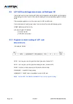
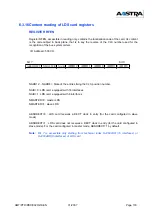
Page 116: ...d under enter command prompt with following syntax VPORT ADR aaaa GP xx CLX y with aaaa register I O address xx cluster number y LDT LDS card number 5 5 1 Register content reading of LDT card REGISTER...

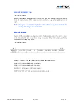
Page 117: ...The reading of this one gives to zero the meter REGISTER RFEN Register RFEN accessible in reading only contains the localization code of the card Its content is the code cabled in back plane that is t...

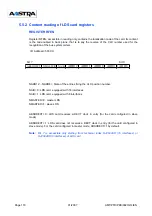
Page 118: ...the CLX position number NA B 0 LDS card equipped with 16 interfaces NA B 1 LDS card equipped with 8 interfaces NMASTER 0 master LDS NMASTER 1 slave LDS ABSHDECT 0 LDS card receives a DECT clock in ent...

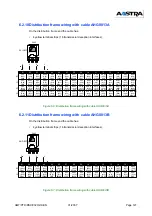
Page 119: ...Configuring the LDT card 6 2 1 References and equipment Table 1 References and equipment Note 1 This cable allows to transmit DECT clock 800 ms by the distribution frame Note 2 New LDT cable to use w...

Page 120: ...R Address not recognised Fault REA5 Rapid LED flashing Card operational Slow LED flashing Card operational REA6 Not significant LED off PM LED steady on Card operational LED off Card not operational 5...

Page 121: ...gure 6 2 Top view of the LDT card J2 0 1 2 3 J1 J2 4 1 2 3 J1 J2 8 1 2 3 J1 J2 12 1 2 3 J1 J2 1 1 2 3 J1 J2 5 1 2 3 J1 J2 9 1 2 3 J1 J2 13 1 2 3 J1 J2 2 1 2 3 J1 J2 6 1 2 3 J1 J2 10 1 2 3 J1 J2 14 1 2...

Page 122: ...c resynchronization Remote power supply configuration straps J1 set to 1 2 Remote power supply ON J2 set to 1 2 Remote power supply ON J1 set to 2 3 Remote power supply OFF J2 set to 2 3 Remote power...

Page 123: ...ation refer to document 12 in the reference documents The LDT card must be connected to a synchronising clock input in the PBX if a T0 interface is synchronising on the LDT card Each group of 8 S inte...

Page 124: ...all the clusters that contain LDT cards to which DECT base stations are connected This configuration is set through the switches on the RMH card The signal 800ms will be transmitted to LDT card accor...

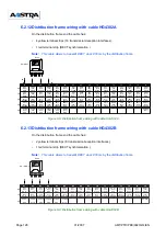
Page 125: ...D PBX 0020 2 4 EN 01 2007 Page 125 Figure 6 4 AHG0013X cable Note New LDT cable must be used if DECT clock 800 ms forwards by the loop case of a PBX equipped with FPS backplane a CSI card and FPG back...

Page 126: ...Page 126 01 2007 AMT PTD PBX 0020 2 4 EN Figure 6 5 HG4302X cable Note This cable allows to transmit DECT clock 800 ms by the distribution frame...

Page 127: ...0 RED RD6 A11 CLEAR NRD6 A12 GREEN ED7 A13 OR ANG E NED7 A14 WHITE RD7 C13 VIOLET NRD7 C14 BLUE ED8 B14 OR ANG E NED8 B15 JAUN E RD8 B12 VIOLET NRD8 B13 BR OWN ED9 B16 OR ANG E NED9 A16 BLACK RD9 C15...

Page 128: ...C08 WHITE ED6 A09 GRAY NED6 A10 RED RD6 A11 CLEAR NRD6 A12 GREEN ED7 A13 ORANGE NED7 A14 WHITE RD7 C13 VIOLET NRD7 C14 BLUE ED8 B14 ORANGE NED8 B15 JAUNE RD8 B12 VIOLET NRD8 B13 BROWN ED9 B16 ORANGE...

Page 129: ...inimum index for transmitting the DECT clock on the loop for sending the DECT clock The plugs used with the LDT cards are AVADQ plugs ref HR5124B Jumpers TOPRAD correctly set on the FPS backplane Conf...

Page 130: ...e loop switches CA1 CA3 and CA4 on the CSI card must be configured as follows factory configuration Default configuration factory configuration of switches CA1 CA3 and CA4 on the CSI card CA1 CA3 CA4...

Page 131: ...ed under enter command prompt with following syntax VPORT ADR aaaa GP xx CLX y with aaaa register I O address xx cluster number y LDT LDS card number 6 3 15Register content reading of LDT card REGISTE...

Page 132: ...The reading of this one gives to zero the meter REGISTER RFEN Register RFEN accessible in reading only contains the localization code of the card Its content is the code cabled in back plane that is t...

Page 133: ...the CLX position number NA B 0 LDS card equipped with 16 interfaces NA B 1 LDS card equipped with 8 interfaces NMASTER 0 master LDS NMASTER 1 slave LDS ABSHDECT 0 LDS card receives a DECT clock in ent...

Page 134: ...Page 134 01 2007 AMT PTD PBX 0020 2 4 EN...

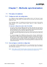
Page 135: ...not duplicated single CSH CSI CUH or CUS card the clock of the second inter site link must be connected to the same CSH CSI CUH or CUS card as the clock of the first link For a device equipped with an...

Page 136: ...mode multisite handover in an F2 and or F4 network is possible provided that bit synchronization 2 048 Mhz clock is carried out by inter site link 7 2 2 Distribution by 3rd pair The base stations of...

Page 137: ...slave radio base station 15 slave radio base station 16 slave radio base station 14 REPEATER REP16 MASTER sync 1st repeater MASTER sync 2nd repeater Power supply PN840B unit or 48v input 48v from PBX...

Page 138: ...16 to 19 Sync 1 to 8 REPEATER REP 96 Power supply LED 21 point female connector N4 21 point female connector N3 21 point female connector N2 21 point female connector N1 syn E17 Gray syn E23 Gray syn...

Page 139: ...YN E17 GND SYN E17 25 24 SYN E15 SYN 16 SYN E15 23 SYN E14 SYN 16 SYN E14 22 SYN E13 SYN E13 21 SYN E12 SYN E12 21 pin connector range 20 SYN E11 SYN E11 19 SYN E10 EN G2 SYN E10 18 SYN E9 GND SYN E9...

Page 140: ...on port This cable carries the multi frame and bit clocks Figure 7 5 Multi site synchronization with OCT4 OCT4I Each OCT4 OCT4 I card has two synchronization ports RJ45 connectors a secondary port J6...

Page 141: ...m Compensation for slave site 1 8x1 50 58 m compensation 100m Compensation for slave site 2 8x2 50 200 266 m compensation 300m Compensation for slave site 3 8x3 50 200 27 301 m compensation 400m Note...

Page 142: ...ring Duplex mode two PBXs are configured in Master mode and are capable of supplying the entire multi site network with the DECT synchronization signal One of the two PBXs must be configured via MMC i...

Page 143: ...is assumed that the two masters priority and not priority are connected to the PSTN network The priority master supplies the entire multi site network with the synchronization single S EXT S DECT and...

Page 144: ...ode series wiring The two Master PBXs are connected via their primary port The Slave PBXs are connected in series from the secondary ports of the Master PBXs P S ADS300 P S ADS300 Ma tre Prioritaire E...

Page 145: ...3 L4 1745 m The sum of the lengths of the two intermediate sections must be less than 600 meters If the series wiring includes only one Slave the length of the synchronization cable linking the Slave...

Page 146: ...onization cables used between the secondary port of the Master and the primary port of the slave Mixed wiring Duplex mode Figure 7 11 Multi site synchronization with UCT L UCT S in Duplex mode mixed w...

Page 147: ...iring of synchronization ports Master Slave and Slave Slave Priority Master Not priority Master wiring ISDN straight wiring Tableau 13 Wiring of synchronization ports priority Master not priority Mast...

Page 148: ...T synchronization and the 2 048 MHz bit synchronization to from another PBX it determines the compensation to make on the DECT clock received according to the distance of the transmitting PBX and retr...

Page 149: ...ype of PBX downstream GAVF1 6 set to ON defines an F1 F6 PBX downstream GAVF1 6 set to OFF defines an F4 PBX downstream Check the configuration of switches CA1 CA3 and CA4 on the CSI card Their config...

Page 150: ...and thus a delay of 0 seconds Check the configuration of switches CA1 CA3 and CA4 on the CSI card Their configuration must be the same as the factory configuration see mono site synchronization Check...

Page 151: ...ts The synchronization port on an F4 has a wiring restriction when a repeater is used downstream of an F4 all the PBXs downstream of the repeater must be of the same type F1 F6 or F4 STATE EXPLANATION...

Page 152: ...nal functions is only compatible on NeXspan S L D with software release R4 1 and above 1 use a repeater if there are more than 5 slave base stations 2 even in an IP multi site network as the IP networ...

Page 153: ...he distribution frame terminal strip 4G Note F2 has no synchronization ports so for a multisite synchronization between an F2 F4 fitted with FPHBG CSH or an F2 F4 fitted with FPHBG2 CSI BCSI the confi...

Page 154: ...J14 jumper on an LD4NX card and used to implement additional functions is only compatible on NeXspan S L D with software release R4 1 and above 1 use a repeater if there are more than 5 slave base sta...

Page 155: ...st be declared master and the other LDS LDT cards slave The master card 800 ms clock SYN outgoing differential signal must be connected to the slave card via the distribution frame terminal strip 4G 1...

Page 156: ...ional functions is only compatible on NeXspan S L D with software release R4 1 and above 1 use a repeater if there are more than 5 slave base stations 2 even in an IP multi site network as the IP netw...

Page 157: ...the DECT base stations are connected to the integrated S0 accesses of a NeXspan S CPU board a third pair is required for synchronization Note The LD4X mode removing the J14 jumper on an LD4NX card an...

Page 158: ...stations are connected to the integrated S0 accesses of the NeXspan S CPU card a third pair is required for synchronization Note The LD4X mode removing the J14 jumper on an LD4NX card and used to impl...

Page 159: ...integrated S0 accesses of the NeXspan S CPU card a third pair is required for synchronization Note The LD4X mode removing the J14 jumper on an LD4NX card and used to implement additional functions is...

Page 160: ...Page 160 01 2007 AMT PTD PBX 0020 2 4 EN...
Page 161: ...8 1 Preliminary operations It is advisable to back up the customer configuration before beginning DECT programming Be sure to have the following information available the PARI number deployment infor...

Page 162: ...istribution frame and note the impedance of the wiring base station assembly for the 2 or 3 pairs The values observed must be the same for the transmit and receive pairs The clock pair impedance must...

Page 163: ...ype data routing menu 2 5 Data management Routes 2 MANAGING TOPOLOGY Declare the cells Declare the DECT parameters 3 MANAGING RESOURCES Name the trunk groups Define a trunk group 4 PUTTING THE DECT SY...

Page 164: ...anagement 9 2 2 DECT parameters MENU 1 8 1 3 Single company management or 1 9 1 3 Multi company management Note For a multisite network additional parameters appear making it possible to define the li...

Page 165: ...CLOCK SYNCHRO this line is used to configure the synchronisation of DECT clocks 3 options Priority master Not priority master Slave Case of a mono site configuration the default value for a site is Pr...

Page 166: ...ll Cells are associated with trunk groups in two phases the first involves naming the trunk groups these names are chosen by the system installer the second phase involves associating the previously d...

Page 167: ...clare a DECT trunk group in a cell all base stations in the cell must be out of service The number of base stations in a cell must never exceed 8 9 3 5 Checking the trunk group declaration Check the r...

Page 168: ...declared on the S0 accesses of the various S0 interface cards Depending on previous subscriber registrations all the subscribers declared on these accesses must be checked and if necessary deleted Us...

Page 169: ...DECT interfaces of the CPU card are in position 0 02 Select IN SERVICE MOTHER BOARD MANAGEMENT MIGRATION UCT HARDWARE VIEW SOFTWARE VIEW XXS CONFIGURATION XXS DIG IN 0 00 IN SERVICE ANAL IN 0 01 IN SE...

Page 170: ...indicates the type of base station 2 or 4 channel BELONGS TO TRUNK GROUP this parameter indicates the name of the PBX trunk group linked to the base station MOBILE RECORDING ALLOWED this parameter mus...

Page 171: ...the majority of cases enter AUTOMATIC DISTANCE FROM MASTER BS 1 If synchronization is via the M bit the distance is that between the base station and the S0 interface master card 2 If synchronization...

Page 172: ...y coverage This menu allows you to display the base stations declared according to the following parameters Location in the PBX Type Status FREE OUT OF SERV LOADING Associated trunk group Cell in whic...

Page 173: ...console and internal calls will receive the busy tone 4 In the TELEPHONY MANAGEMENT menu under EXTENSION DATA it is possible to modify the subscriber s restrictions and features Menu 1 1 1 Extension c...

Page 174: ...3 Display mobiles MENU 1 8 3 3 single company or 1 9 3 3 multi company Note Subscriber 7552 has been created and is awaiting registration Subscriber 7542 has been deleted DELETE MOBILES FIRST DIRECTOR...

Page 175: ...ct COMPANY DEPT or the RESSOC tool this requires a system reload 6 Put the cards in service To position and put into service LDS LDT software variant 23 for LDS and 28 for LDT cards use the MMC XETBLS...

Page 176: ...cells The area to which cells belong is always 0 In multi site configuration if the coverage areas overlap you are advised to select different cell numbers for each of the sites see chapter 13 Multi...

Page 177: ...while to back up the configuration Regular backups must be made throughout the progression of the operations 14 After mobile declaration Put the base stations in service one at a time and check that t...

Page 178: ...ork ID field for local analysis is set to yes ROUTING AND ANALYSIS Obj ROUTING Action Display Routing 0 Type of routing LOCAL TO STANDARD SUBSCR Back up routing for routings Routing used for analysis...

Page 179: ...ected The number 999000 is assigned to the first PLL 999001 to the second etc The PLLs are created automatically when the base stations are created TOTAL GROUPS Obj Total groups Action Display Input b...

Page 180: ...company department profile Association of a company profile using the MMC XACHMT object COMPANY SERVICE or using the RESSOC tool this requires a system reload In a real multi company configuration ass...

Page 181: ...the following parameters in the MMC XETBLS action Equipment cluster number 2 to 39 corresponding to the card slot SBL family BOARDS SBL sub family CLX Board Type LDS LDT 32 TS or LDS LDT 64 TS CLX boa...

Page 182: ...cell is 8 you are advised to configure only 6 with a view to expansion in order to increase traffic flow It may be necessary to declare several cells The Registration zone is always 0 In multisite con...

Page 183: ...295 FFFF FFFFh The value of the random number has no significance However in a multi site configuration the number must be identical in all locations where the mobiles are to be registered LLP Radst p...

Page 184: ...e and a trunk group number with a cell number This trunk group represents the resources in the cell and is used to associate the cell number with a physical equipment interface TRUNK GROUP AND TRUNKS...

Page 185: ...s IN SERVICE Bus short TS Frame assignment 111111111111 Freq assignment 1111111111 11 0 9 0 Anten choice Automatic Inscript Radio Stat YES Type of RadSt BIT_M Distance master RadSt 0 to 100m TRUNK GRO...

Page 186: ...es must declared with cell 0 as the reference cell SYSTEM PARAMETERS Ctrl H Help Object Password Type of password Cordless Registration Action Modify Password Operation Password TELEPHONE SUBSCRIBERS...

Page 187: ...the sites Same RANDOM registration number on all the sites Same RS registration number on all the sites Same MOBILE registration password on all the sites Example MMCs for a contiguous multi site con...

Page 188: ...ones field Zone sub object General field Addr nat F4 2nd byte BF All sites of all centers on NeXspan C S L menu 1 8 1 2 or 1 9 1 2 DECT Parameters parameter search mobiles not registered Create a broa...

Page 189: ...OR IN THE LIST with a broadcast list broadcast list A is the default Program the menu 3 7 2 5 with a list of the remote sites and centres DECT PARAMETERS PARI VALUE 0 999999999 RANDOM VAL RECORDED 86...

Page 190: ...66 DIR BEGINNING ASSIGNED TO PLL 999 SEARCH MOBILES NOT REGISTERED IN THE LOCAL SITE NO OR IN ANOTHER SITE OR IN THE LOCAL CENTER NO OR IN ANOTHER CENTER OR IN THE LIST BROADCAST A CLOCK SYNCHRON MAST...

Page 191: ...r the compensation distance is 100 meters and the maximum value 2000 meters The line CURRENT STATE gives the current state of DECT synchronization The possible states are transmitter transmitter netwk...

Page 192: ...riority Master Note The line CURRENT STATE gives the current state of DECT synchronization The possible states are transmitter transmitter netwk clk transmitter local clk receiver receiver not OK rece...

Page 193: ...the section synchronization with UCT L UCT S applied The minimum value for the compensation distance is 100 meters and the maximum value 2000 meters DECT PARAMETERS PARI VALUE 0 999999999 RANDOM VAL R...

Page 194: ...ansmitter transmitter netwk clk transmitter local clk receiver receiver not OK receiver polarity OK and receiver polarity not OK It is thus possible to know whether the clock is taken from the network...

Page 195: ...2000 meters DECT PARAMETERS PARI VALUE 0 999999999 RANDOM VAL RECORDED 86 RS VAL RECORDED 66 DIR BEGINNING ASSIGNED TO PLL 999 SEARCH MOBILES NOT REGISTERED IN THE LOCAL SITE NO OR IN ANOTHER SITE OR...

Page 196: ...0 2 4 EN 11 6 Multi site configuration with CSI In a multi site configuration with CSI there is no particular MMC programming to be carried out Configuration is manual configuration of switches on BCS...

Reviews: