Page 124
01/2007
AMT/PTD/PBX/0020/2/4/EN
6.2.8 DECT CLOCK INTERFACES
The CSI card generates a DECT clock and sends this clock to all the PBX clusters. The
synchronization signal is sent via the loop and extracted by the RMH cards. The DECT
synchronization signal is then sent to the LDT cards via the backplane. The configuration rules
are as follows:
•
The DECT base stations must be configured in synchronization mode by the M bit.
•
The LDT cards must all be configured in "Slave" mode.
•
For co-located clusters: there is no transmission delay on the loop. The adjustment is exactly
the same on all the RMH cards (Value V=1). Therefore, the switches must be configured as
follows (factory setting):
"CA3-3 and CA3-4 = OFF
"CA2 + CA1 + CA3-1,2 = ON
Note :Binary value: ON = 0; OFF = 1
•
For remote clusters: the transmission time compensation on the loop must be configured in
the RMH card(s) of all the clusters that contain LDT cards to which DECT base stations are
connected. This configuration is set through the switches on the RMH card.
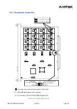
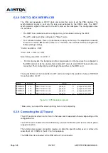
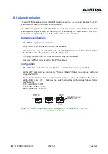
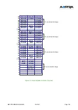
The signal 800ms will be transmitted to LDT card according to the position of jumper TOPRAD
for each position of LDT
Figure 6-3: FPS backplane jumpers
* Make sure you respect the screen printing; there is no foolproofing
6.2.9 Connecting the LDT board
The LDT card is inserted in a CLX slot in the base and/or expansion shelves depending on the
configuration file.
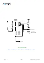
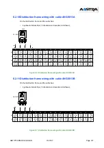
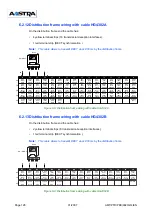
The LDT card is connected to the distributor by a special cable also used for the remote power
supply connection.
The remote power supply connection requires a cable (the specific cable) used to retrieve the
subscriber's 40 V ISDN or the 48 V on the backplane.
The ISDN clock is connected to the RSU with a 21-pin connector.
Nam e Position
Using
TOPRAD
J13
DECT CLX7 clock
present
=>
jum per set to ON *
TOPRAD
J16
DECT CLX2 clock
present
=>
jum per set to ON *
TOPRAD
J19
DECT CLX1 clock
present
=>
jum per set to ON *
TOPRAD
J22
DECT CLX0 clock
present
=>
jum per set to ON *
Summary of Contents for NeXspan C
Page 2: ...Page 2 01 2007 AMT PTD PBX 0020 2 4 EN...
Page 20: ...Page 20 01 2007 AMT PTD PBX 0020 2 4 EN...
Page 66: ...Page 66 01 2007 AMT PTD PBX 0020 2 4 EN...
Page 70: ...Page 70 01 2007 AMT PTD PBX 0020 2 4 EN Figure 4 2 Bottom view of the LD4 ST card...
Page 134: ...Page 134 01 2007 AMT PTD PBX 0020 2 4 EN...

