AMT/PTD/PBX/0020/2/4/EN
01/2007
Page 137
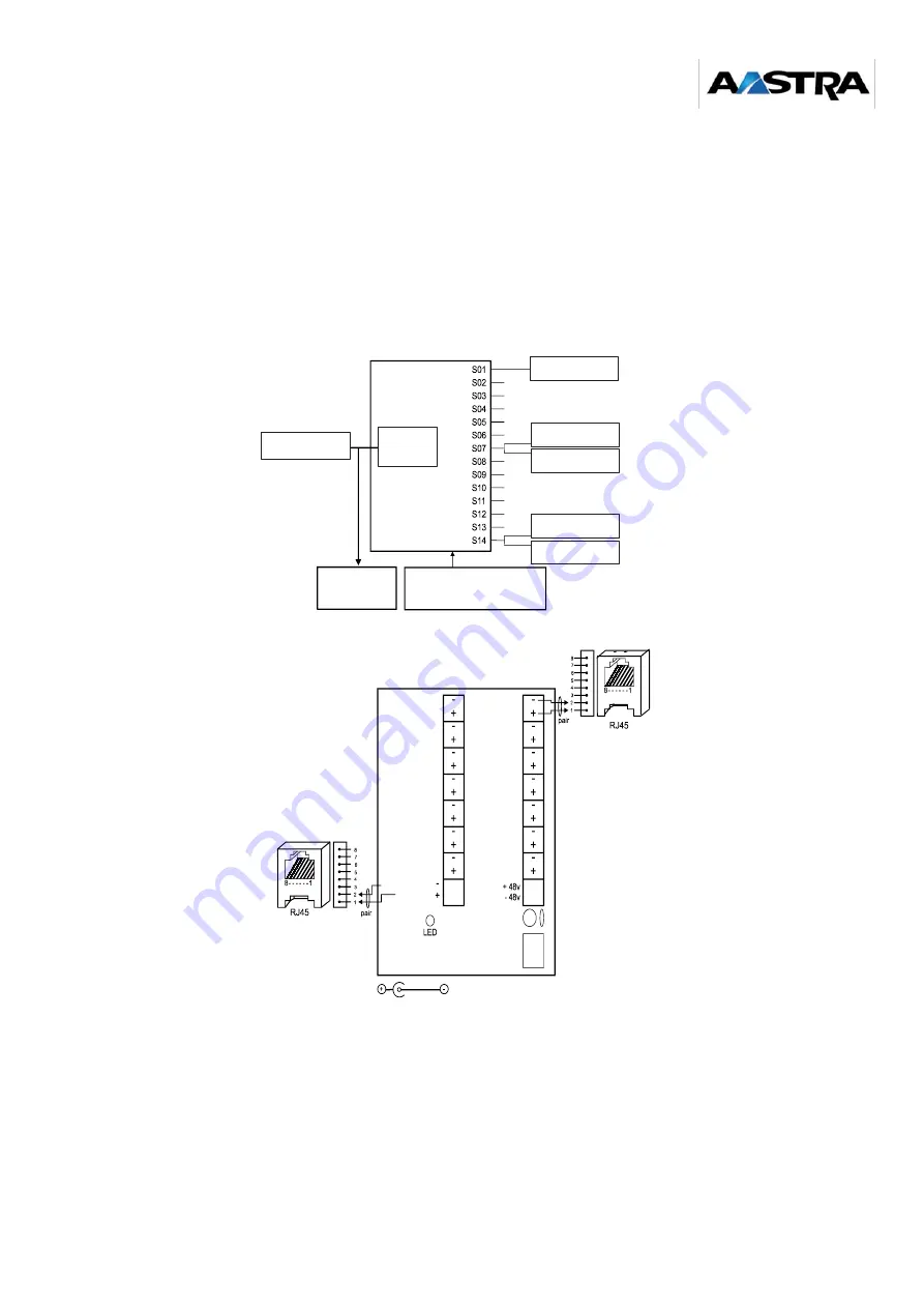
Wiring synchronization with the REP16 repeater
Description of the REP 16 repeater
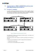
It is possible to connect:
•
only one base station per repeater output (two base stations on outputs 7 and 14)
•
one to four repeaters to the master base station.
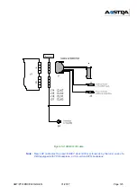
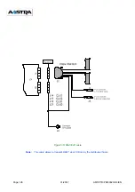
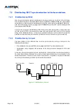
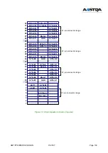
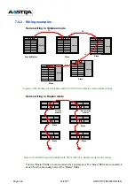
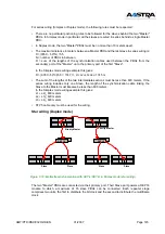
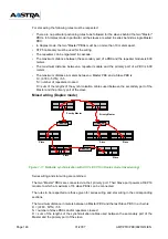
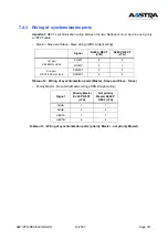
Figure 7-2: Wiring synchronization with the REP16 repeater
MASTER
Radio base station
slave
radio base station 1
slave
radio base station 7
slave
radio base station 15
slave
radio base station 16
slave
radio base station 14
REPEATER REP16
MASTER
sync
(1st repeater)
MASTER
sync
(2nd repeater)
Power supply
- PN840B unit
- or -48v input / -48v from PBX
MASTER
Radio
base
station
Radio
base
station
SLAVE
MASTER
Clock input
Radio base
station 08
Radio base
station 09
Radio base
station 10
Radio base
station 11
Radio base
station 12
Radio base
station 13
Radio base
station 14 and 16
Radio base
station 01
Radio base
station 02
Radio base
station 03
Radio base
station 04
Radio base
station 05
Radio base
station 06
Radio base
station 07 and 15
40/48 VDC power supply
Summary of Contents for NeXspan C
Page 2: ...Page 2 01 2007 AMT PTD PBX 0020 2 4 EN...
Page 20: ...Page 20 01 2007 AMT PTD PBX 0020 2 4 EN...
Page 66: ...Page 66 01 2007 AMT PTD PBX 0020 2 4 EN...
Page 70: ...Page 70 01 2007 AMT PTD PBX 0020 2 4 EN Figure 4 2 Bottom view of the LD4 ST card...
Page 134: ...Page 134 01 2007 AMT PTD PBX 0020 2 4 EN...

