AMT/PTD/PBX/0020/2/4/EN
01/2007
Page 59
Metal structures found in conference halls and production rooms can also cause radio waves to
be reflected due to their large metal structures. The resulting interference reduces the base
station’s range.
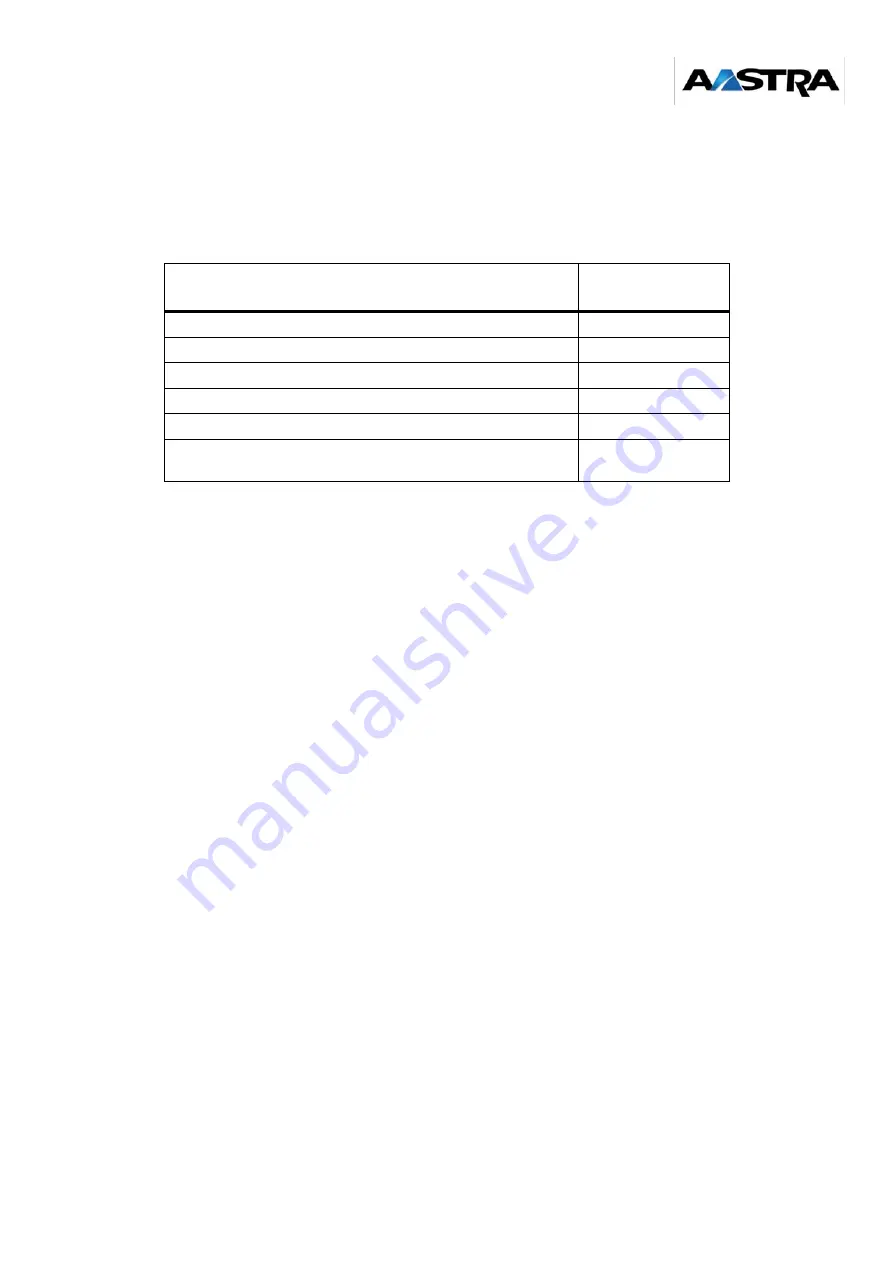
Once the nature of the materials has been identified in the coverage areas, the size of the radio
areas can be evaluated, taking the following information into account:
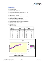
(*) : using integrated antennas
Table1: Evaluation of radio area size for each type of premises
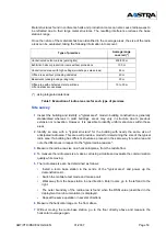
Site survey
1
Inspect the building and identify a "typical area": modern building construction is generally
standardised whereas in older buildings, areas may vary in structure due to previous
extension or renovation. However, it is possible to identify uniform structures within these
areas.
2
Identify an area with a "typical structure" for the building with nearly the same size of
anticipated radio area. This area will provide a model for determining the size of the typical
radio area. If a building has different structures, proceed in the same way for each area and
note the differences in respect to the "typical radio area size".
3
Measure the radio area size on a horizontal plane, from the middle floor.
4
To measure the radio area size, make a call using a mobile and evaluate the communication
quality while moving.
5
The radio area size can be determined as follows:
•
Install a radio base station in the centre of the "typical area" and power up the
demonstration kit.
•
Switch the mobile to test mode and make a call.
•
Walk away from the base station in one direction. Enter rooms, go to the left and to the
right.
•
The outer boundary of the radio area is found when the RSSI value (described in the
deployment tool documentation) is displayed.
•
Repeat the same operation in several directions.
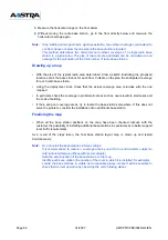
6
Measure the horizontal range on the floor above.
7
Without moving the radio base station, go to the floor directly above and measure the
horizontal coverage again.
Type of premises
Average range
covered (*)
Unobstructed outdoor areas (parking lots)
200/300 m
Exhibition halls or production rooms without protrusions
100 m
Unobstructed areas with high ceilings (workshops, sales areas)
60 m
Office areas without protruding obstacles
40 m
Basements (underground parking lots)
20 m
Office area with obstacles, metal partitions
Lift and stairs access areas
10 to 30 m
Summary of Contents for NeXspan C
Page 2: ...Page 2 01 2007 AMT PTD PBX 0020 2 4 EN...
Page 20: ...Page 20 01 2007 AMT PTD PBX 0020 2 4 EN...
Page 66: ...Page 66 01 2007 AMT PTD PBX 0020 2 4 EN...
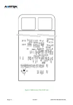
Page 70: ...Page 70 01 2007 AMT PTD PBX 0020 2 4 EN Figure 4 2 Bottom view of the LD4 ST card...
Page 134: ...Page 134 01 2007 AMT PTD PBX 0020 2 4 EN...

