background image


Standard controller  –


Installation manual 


AAT SYSTEMY BEZPIECZEŃSTWA Sp. z o.o.


                     All rights reserved.


5


3. General guidelines for controller installation


• 

Before controller installation please read this manual.


• 

Controller installation can be performed only by qualified personnel with the 

appropriate certificate, authorizing to install and service such equipment


• 

Controller  should  be  installed 

inside  protected  area

  with  temperature 

above +2°C and normal humidity.


• 

Controllers should be located so that the minimum distance from the cables 

and high voltage devices and other devices, that  generate electrical noise, 

was 2 m. The minimum distance from the telephone line should be 1 m, and 

from transmitting devices 8 m. 


• 

Controller should be powered from dedicated power supply, type APSAAT4, 

described in further part of manual


• 

Wire connections and works with  internal controller parts with  power on is 

strictly prohibited, as it may damage the device


• 

Before  connecting  controller  to  power  supply,  all  necessary  connections 

should be made, in accordance with this manual.
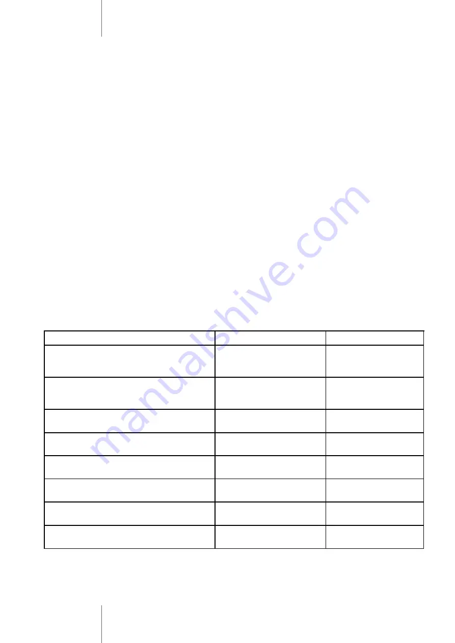
 

Connection


Wire type


Distance


Ethernet switch (or router) 


> IP controller


UTP

-

5 twisted

-

pair wire 

with RJ45 connectors


Up to 50 m 

(recommended)


(max. 100m)


KDH

-

MOD2000 module > Controller


(located out of enclosure)


2 pairs of


UTP

-

5 twisted

-

pair wire


Up to 800m 

(recommended)


(max. 1200m)


Reader > Controller


6

-

core LIYCY 6x0,75 or 

UTP

-

5 twisted

-

pair wire


Up to 60m max.


Emergency exit button > Lock > 


Controller


2 or 4

-

core cable


(4×1.0)


150m


Door contact > Controller


2

-

core cable


(2×0.5)


150m


Exit button > Controller


2

-

core cable


(2×0.5)


150m


Detector > Controller input


2

-

core cable


(2×0.5)


150m


Mains power supply 230VAC


3

-

core cable


(3×1.5)


Connection wires table


Summary of Contents for KaDe KDH-KS3012-IP

Page 1: ...EADER KDH C130U BLACK KDH C130M BLACK KDH CK130U BLACK KDH CK130M BLACK WERSION 2 0 28 11 2018 Installation Manual PROXIMITY CARD READER KDH C130U BLACK KDH C130M BLACK KDH CK130U BLACK KDH CK130M BLA...

Page 2: ...idelines for controller installation 5 4 KDH KS3024 IP controller module 6 5 Reader exit button and sensor connection 7 6 Power supply lock Ethernet door sensor and I O module connection 8 7 APSAAT4 p...

Page 3: ...trollers are also provided with additional RS485 port in order to connect extension module MOD2000INOUT List of the most important controller features and parameters is presented in attached table Sys...

Page 4: ...CP Extension modules connection RS485 dedicated port Readers cards readers ports 4 ports Wiegand interface card formats 26 34 bit Wiegand self defined card types Compatible with reader technology keyp...

Page 5: ...edicated power supply type APSAAT4 described in further part of manual Wire connections and works with internal controller parts with power on is strictly prohibited as it may damage the device Before...

Page 6: ...Relay output RL1 Power supply 12 VDC Reader port RDR 1 Reader port RDR 2 Reader port RDR 3 Reader port RDR 4 Exit button door 1 Exit button door 2 Exit button door 3 Exit button door 4 Alarm input 1 A...

Page 7: ...YELLOW OUT BUZ1 MOD YELLOW OUT BUZ2 MOD GREEN WHITE BROWN BLACK RED GREEN WHITE BROWN READER D3 READER D4 YELLOW OUT BUZ3 MOD YELLOW OUT BUZ4 MOD BUTTON D2 ALARM LINE 1 ALARM LINE 2 ALARM LINE 3 ALAR...

Page 8: ...ore modules with different addresses to one controller PSU 12VDC Integrated in APSAAT4 Lock NC type lock Lock NO type lock Alarm siren I O module Switch TCP RS485 A RS485 B RS485 GND 1 C 1 NC 1 N0 1 A...

Page 9: ...uts relay and transistor with LED indication EPS technical output for absence of AC supply PSU output signalling absence of DC voltage power supply failure LoB output signalling low battery voltage Ab...

Page 10: ...t AUX 1 12VDC with controller terminals additional terminals on controller module supply socket can be connected to I O module according to figure on previous page connect controller RS485 port using...

Page 11: ...h controller Procedure for creating programming card 1 Push the button Mode located on the upper edge of controller and hold it for 3 seconds Read any card in the reader it will be programming card To...

Page 12: ......

Reviews: