®
PROFESSIONAL SERIES
Make sure all PB7000 Senders and PB7000 Receivers have
Correct Video Channel setting.
Scenario
1 to 1,1 to Many
Multicast w/ Dip Switch Matching
Multicasting w/ VLAN
Power On Senders and Receivers (Plug-in DC adapter).
Connect all sources to each Sender with HDMI cable.
Plug IR Emitter cable into IR Emitter port on PB7000
Sender for IR Pass Thru function. Place IR Emitter toward
the IR receiving window of video source. Plug IR Receiver
cable into IR Receiver port on PB7000 Receiver, place IR
Receiver toward to IR Remote location.
Connect all displays to Receiver by HDMI cable, or VGA
cable if non-HDCP video source.
Connect all PB7000 Senders and Receivers to Gigabit
Ethernet Switch (8K Jumbo Frame/IGMP enabled) with
Cat5e cables.
If 1 to 1 extender, Connect Sender and Receiver with
Cat5e cable to its RJ-45 directly.
Power On Displays and Video Sources, Play Video.
Multicast w/ Dip Switch Matching
Setting up a unique Video Channel setting on each
PB7000 Sender with video source. Make sure the setting
on each sender won’t be duplicated.
On Video Channel Setting, PB7000 Receivers' Video Chan-
nel selection always match that of the Senders with the
video sources you want to display.
Following Standard Installation procedure to setup all
senders and receivers connected to Gigabit switch.
Receiver Change Video Channel
Change Dip Switch, after two seconds, it will change
video channel automatically.
Use IR Remote control, toward to IR receiver connected
to Receiver, and press Video Channel number button.
MultiCasting with Layer 2 Managed Switch
Make Sure Same Video Channel setting on all PB7000
senders and PB7000 receivers.
Managed Switch with 802.1Q VLAN
Only One Sender is allowed in Each VLAN Group.
Multiple Receivers Ok in Each VLAN Group.
Following Standard Installation procedure to connect all
senders and receivers to managed switch.
Dip Switch
All Same
Refer Instruction below
All Same
Broadcasting & MultiCasting Installation
1
1
2
2
1
2
3
1
2
3
3
4
5
6
7
Video Mode Switching
(By Short Press of Receiver EDID button)
- Video mode(Auto) Smooth Motion, Auto switch between video
mode and Grpahic mode depends on motion of video.
- Graphics mode Fixed at High Video Quality & Sharp Clear Detail,
but High Bandwidth Required.
Display EDID Copy
1. On Receiver web page, Click “Functions” Tab
2. Check “Copy EDID from this Video Output” and Click Apply
3. Reboot Sender and Receiver
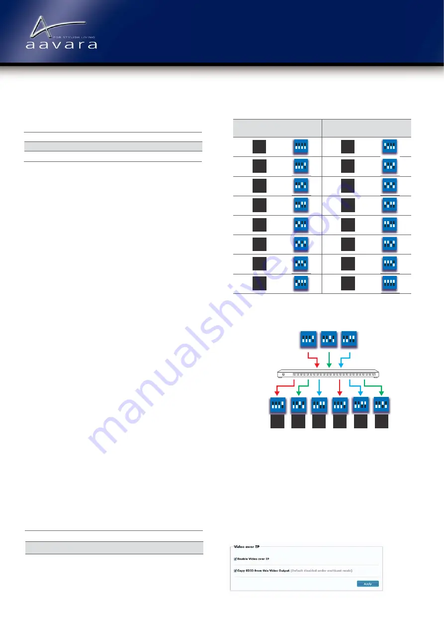
Video Channel Matching Config Example
Video Channel Matching Table
Receiver OSD
Video Channel #
Sender Dip
Switch Setting
Receiver OSD
Video Channel #
Sender Dip
Switch Setting
1 2 3 4
ON
1 2 3 4
ON
1 2 3 4
ON
1 2 3 4
ON
1 2 3 4
ON
1 2 3 4
ON
1 2 3 4
ON
1 2 3 4
ON
1 2 3 4
ON
1 2 3 4
ON
1 2 3 4
ON
1 2 3 4
ON
1 2 3 4
ON
1 2 3 4
ON
1 2 3 4
ON
1 2 3 4
ON
1 2 3 4
ON
4
ON
1 2 3 4
ON
1 2 3 4
ON
2
4
ON
1 2 3 4
ON
Media
Player
Gigabit Switch
(Jumbo Frame/IGMP enabled)
Video
Source
PB7000
Sender
Setting
Receiver
Video Channel
OSD
Receiver Setting
Display
Content
PS3
1 2 3 4
ON
1 2 3 4
ON
1 2 3 4
ON
PC
Media
Player
Media
Player
PS3
PS3
PC
PC
1
9
10
11
12
13
2
3
4
2
3
3
4
4
2
5
6
7
8
14
15
16
Aavara
®
PB7000 HDMI USB KVM/Broadcaster Quick Start Guide
* If use IR Remote control to change Video Channel, OSD number will not
match Dip Switch setting.
1 2 3 4
ON
1 2 3 4
ON
Summary of Contents for PB7000
Page 1: ......


