background image


15


over during use when the fuel warms up 

even with the fuel cap in place. 


4. After refueling, make sure the tank cap 

is tightened securely. 

5. Wipe up any spilled fuel immediately 

with a clean, dry, soft cloth, since fuel 

may deteriorate painted surfaces or 

plastic parts. 

IMPORTANT:


Use only unleaded gasoline. The use of 

leaded gasoline will cause severe damage 

to internal engine parts. 
• Never use an oil/gasoline mixture. 

• Never use old gasoline. 

• Avoid getting dirt or water into the fuel 

tank. 

• Gasoline can age in the tank and make 

starting difficult.


Never store 

generator for extended periods of 
time with fuel in the tank. 


NOTE

: Fuel deteriorates over 

time. It may be DIFFICULT to 


start the engine if you use fuel which 

has been kept for more than 30 days. 

Towards the end of the season, it is 

advisable to put only as much fuel in 

the tank as you need for each use, since 

it should be completely used up before 

storing the product. Empty remaining 

fuel from the tank and the 

CARBURETTOR when storing the 

product for over 30 days. 


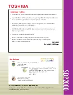
Step 3-GROUND (Earth) THE 
GENERATOR


WARNING:


Make sure to 

ground (earth) the generator. Failure to 

properly ground the generator can result 

in electrocution. 
Ground the generator by tightening the 

grounding nut on the front control panel 

against a grounding wire. A generally 

acceptable grounding wire is a No. 12 

AWG (American Wire Gauge) stranded 

copper wire. This grounding wire should 

be connected at the other end to a copper, 

brass, or steel-grounding rod that is driven 

into the earth. Wire and grounding rods 

are not included in generator contents. 
Grounding codes can vary by location. 

Contact a local electrician to check the 

area codes. 


STARTING THE 
GENERATOR 

Before starting the generator, make sure 

you have read and performed the steps in 

the “Generator Preperation” section of 

this manual. If you are unsure about how 

to perform any of the steps in this manual 

please call customer service center.


NOTE: 

The generator can be used with the rated 

output load at standard atmospheric 

conditions. 

Standard atmospheric conditions

” 

Ambient temperature 25


Barometric pressure 100kPa 

Relative humidity 30% 

The output of the generator varies due to 

Summary of Contents for A112003

Page 1: ...anual before assembling operating and maintaining this unit You are responsible for operating the product properly safely Version V1 20171123 A A V I X O U T D O O R S 3000W DIGITAL INVERTER GENERATOR...

Page 2: ...35 Wiring diagram 37 A112003 Exploded View Part List 38 SAFETY RULES Read and observe all warnings cautions and instructions on the generator and in this owner s manual before operating your generator...

Page 3: ...hese areas Using a fan or opening windows and doors does NOT supply enough fresh air ONLY use a generator outdoors and far away from open windows doors and vents These openings can pull in generator e...

Page 4: ...rkers Use a ground fault circuit interrupter GFCI in highly conductive areas such as metal decking or steel work GFCIs are available in line with some extension cords Do not use in rainy conditions Do...

Page 5: ...ion and power supply cords for damage resulting from vibration Have damaged items repaired or replaced as necessary Do not use plugs or cords that show signs of damage such as broken or cracked insula...

Page 6: ...ng s electrical system a licensed electrician must install an isolation transfer switch in the building s main fuse box The switch is the connection point for generator power and allows selection of g...

Page 7: ...ength should not exceed 1 60 meters 196ft for cross section of 1 5 mm square 2 100 meters 328ft for cross section of 2 5 mm square This extension cord should be protected by a tough flexible rubber sh...

Page 8: ...well and without chips mud and water come in it may damage the engine inverter or alternator if the cooling vent blocked Do not mix the generator with other stuff If moving storing or running the uni...

Page 9: ...B Port 5V 1 A 2 1A Phase Single Engine Engine Type Single cylinder 4 stroke forced air cooling OHV Displacement cc 192 Fuel Type Unleaded Gasoline Fuel Tank Capacity 3 9 US gallon 15 liters Fuel Consu...

Page 10: ...Air intake 2 Fuel tank cap 6 Recoil starter 3 Draw handle 7 Louver 4 Control panel 8 Muffler Accessories 1 Socket Wrench 1pc 2 Oil funnel 1pc 3 Screw driver 1pc 4 12V DC Battery charging cable 1pc 5 S...

Page 11: ...his manual are a guide but not necessarily an exact copy of the actual product CONTROL FUNCTION Engine switch The engine switch controls the ignition system 1 OFF Insert the key provided ignition circ...

Page 12: ...ect current is not output CAUTION Reduce the load of the connected electric device below the specified rated output of the generator if the DC protector turns off If the DC protector turns off again s...

Page 13: ...you are unsure about how to perform any of the steps please call customer service center Failure to perform these steps properly can damage the generator or shorten its life Step 1 ADD OIL The genera...

Page 14: ...rmly before closing the access panel Step 2 ADD GASOLINE DANGER This generator may emit highly flammable and explosive gasoline vapors which can cause severe burns or even death if ignited A nearby op...

Page 15: ...when storing the product for over 30 days Step 3 GROUND Earth THE GENERATOR WARNING Make sure to ground earth the generator Failure to properly ground the generator can result in electrocution Ground...

Page 16: ...O alarm in the home If you start to feel sick dizzy or weak after the generator has been running move to fresh air RIGHT AWAY See a doctor You may have carbon monoxide poisoning WARNING This generator...

Page 17: ...does not stop when press the choke knob full in 10 Push the choke knob fully in 11 Allow the generator to run for several minutes before attempting to connect any electrical devices This allows the g...

Page 18: ...the engine runs at normal speed continuously STOPPING THE GENERATOR To Stop The Generator 1 Turn off any electric devices prior to unplugging them from the generator NOTE Unplugging running devices ca...

Page 19: ...t it from damage The oil level of the engine should be checked before each use to ensure that the engine crankcase contains sufficient lubricant To check or add oil follow these steps 1 Place the gene...

Page 20: ...nerally acceptable grounding wire is a No 12 AWG American Wire Gauge stranded copper wire This grounding wire should be connected at the other end to a copper brass or steel grounding rod that is driv...

Page 21: ...e rated or running wattage of each device This number should be listed somewhere on the device or in its instruction manual If this wattage cannot be found calculate it by multiplying the Voltage requ...

Page 22: ...1 Device Requir ement s Amps 2 5 5 7 5 10 15 Watts 120V 300 600 900 1200 1800 Max Cord Lengt h ft by Wire Gauge 8 wire NR NR NR NR NR 10 wire NR NR 350 250 150 12 wire NR 300 200 150 100 14 wire 375...

Page 23: ...they lie within the supply ranges given in the above table Consult the equipment manufacturer for further advice ALTERNATING CURRENT CONNECTION NOTE Make sure to ground Earth the generator When the e...

Page 24: ...and then restarted The overload indicator light Red may come on for a few seconds at first when using electric devices that require a large starting current such as a compressor or a submergible pump...

Page 25: ...over eyes when working near batteries KEEP OUT OF REACH OF CHILDREN Charge the battery in the correct procedure by following instructions in the owner s manual for the battery 1 Wind the battery charg...

Page 26: ...ll help prolong the life of the machine and trouble free as well as eco friendly If there are any questions about the maintenance procedures listed in this manual please call our service center Recomm...

Page 27: ...in your engine do it as soon as possible WARNING Stop the engine before servicing Put the engine on a level surface and remove the spark plug cap to prevent the engine from starting Do not operate the...

Page 28: ...ing under heavy load or high ambient temperatures It is also necessary to drain the oil from the crankcase if it has become contaminated with water or dirt The oil capacity of the generator engine is...

Page 29: ...ith hand while testing You should periodically remove and inspect the spark plug The spark plug is important for proper engine operation which should be checked periodically A good spark plug should b...

Page 30: ...olts 1 put the screw 1 4 in the access panel but donot tighten it fully 2 put the screw 3 6 in the access panel but donot tighten it fully 3 put the screw 2 5 in the access panel but donot tighten it...

Page 31: ...riginal position 9 Reinstall the access panel and tighten the screw 1 put the screw 1 4 in the access panel but donot tighten it fully 2 put the screw 3 6 in the access panel but donot tighten it full...

Page 32: ...e muffler screen and spark arrester using a wire brush CAUTION When cleaning use the wire brush lightly to avoid damaging or scratching of muffler screen and spark arrester 5 Check the muffler screen...

Page 33: ...y flammable and poisonous see SAFETY INFORMATION section carefully CAUTION Immediately wipe off spilled fuel with a clean dry soft cloth since fuel may deteriorate painted surfaces or plastic parts 5...

Page 34: ...Pull the recoil starter until you feel compression Then stop pulling This prevents the cylinder and valves from rusting 4 Clean exterior of the generator 5 Store the generator in a cool dry well went...

Page 35: ...face to prevent low oil shutdown from triggering Engine needs maintenance Get a professional engine tune up at an authorized small engine repair shop Generator was tilted when adding oil or shipped si...

Page 36: ...ry connecting a different device Generator is overloaded Overload light is on Perform these steps 1 Turn off all electrical devices 2 Unplug all electrical devices 3 Shut down the engine 4 Wait severa...

Page 37: ...37 WIRING DIAGRAM...

Page 38: ...l 1 A112003 1 6 1 7 30A socket 1 A112003 1 7 1 8 20A socket 1 A112003 1 8 1 9 30A AC protector 1 A112003 1 9 1 10 20A AC protector 1 A112003 1 10 1 11 DC protector 1 A112003 1 11 1 12 USB Voltage stab...

Page 39: ...Muffler Cover 1 A112003 2 3 2 4 Wheel 2 A112003 2 4 2 5 Cross Screw M6X30 4 A112003 2 5 2 6 M10x70 Flange Bolt 2 A112003 2 6 2 7 Bushing 2 A112003 2 7 2 8 Wheel Support 2 A112003 2 8 2 9 Hexagonal Nut...

Page 40: ...t 4 A112003 3 7 3 8 Hexagonal Flange Bolt 51 A112003 3 8 3 9 Limit Speed Part 1 A112003 3 9 3 10 Support Frame 1 A112003 3 10 3 11 Inverter Board 1 A112003 3 11 3 12 Hexagonal Flange Bolt M6x25 4 A112...

Page 41: ...Top Cover 1 A112003 3 32 3 33 Tank Mouth Rubber 1 A112003 3 33 3 34 Mirror 1 A112003 3 34 3 1 Flange Bolt M6X45 2 A112003 3 1 3 2 Gel 1 A112003 3 2 3 3 Groud Foot 2 A112003 3 3 FIG 4 Fuel Tank Compon...

Page 42: ...A112003 5 3 5 4 Hexagonal Flange Nut M14 1 A112003 5 4 5 5 Stator 1 A112003 5 5 5 6 Hexagonal Flange Bolt M6x 55 4 A112003 5 6 5 7 Rotor 1 A112003 5 7 5 8 Flange Nut M6 X 18 4 A112003 5 8 5 9 Alterna...

Reviews: