23
on when total wattage exceeds the
application range. (See “CONTROL
FUNCTION” section for more details.)
CAUTION:
Be sure the total
load is within generator rated
output otherwise generator damage
will occur.
NOTE:
• Some precision equipment is voltage
sensitive and may require a more
uniform voltage supply than portable
generators provide. Examples include
some medical equipment, electronic
controllers, PC, Electronic computers,
microcomputer based equipment or
battery chargers, and some inverters that
sense peak and RMS voltage values.
Consult the precision equipment vendor
before relying on any portable generator
to provide power to such equipment.
• If the generator is to supply medical
equipment, advice should first be
obtained from the manufacturer, a
medical professional or hospital.
• Some electrical appliances or
general-purpose electric motors have
High starting currents, and cannot
therefore be used, even if they lie within
the supply ranges given in the above
table. Consult the equipment
manufacturer for further advice.
ALTERNATING CURRENT
CONNECTION
NOTE:
Make sure to ground (Earth) the
generator. When the electric device is
earthed, always the generator must be
earthed.
CAUTION:
Be sure all electric devices
including the lines and plug
connections are in good condition
before connection to the generator.
Be sure any electric devices are
turned off before plugging it in.
Be sure the total load is within
generator rated output.
Be sure the receptacle load current
is within receptacle rated current.
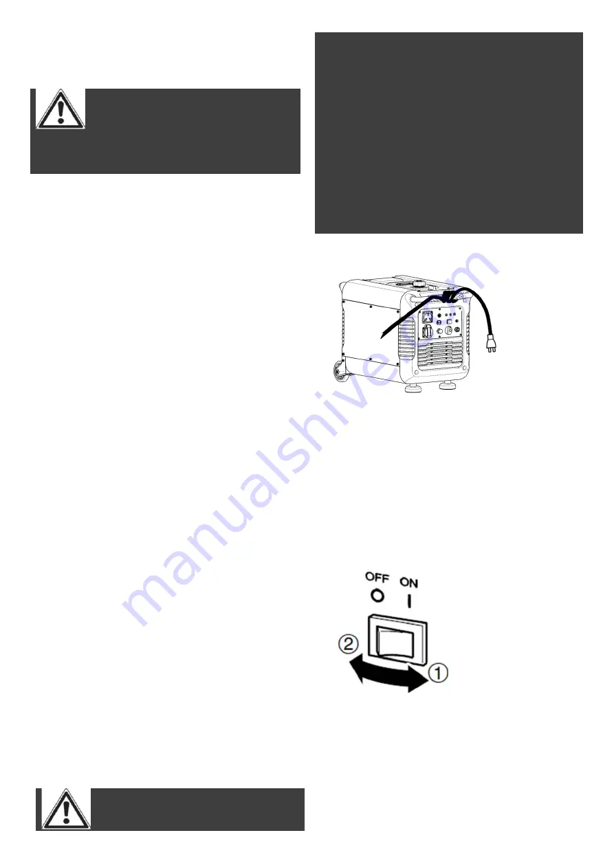
1.
Wind the power lead 2 or 3 turns
around handle.
2.
Start the engine.
3.
Allow the generator to run for several
minutes before attempting to connect
any electrical devices.
4.
Plug in to the AC receptacle.
5.
Make sure the AC pilot light is on.
6.
Turn the economy control switch to
the “
ON
” position and turn on any
electric devices.
NOTE:
The economy control switch must be
turned to “
OFF
” when using electric
devices that require a large starting
current, such as a compressor or a
submergible pump.
Overload indicator light (Red)
Summary of Contents for A112003
Page 37: ...37 WIRING DIAGRAM...


