background image

18

G

B

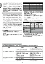
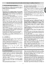
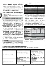
pressure can be regulated in order to optimize use of air-powered tools 

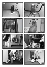
operating on the knob with the valve open (pulling it up and turning it in a 

clockwise direction to increase pressure and counterclockwise to reduce 

this) (

fig. 8

). Once you have set the value required, push the knob down to 

lock it.

• The value set can be checked on the gauge (for versions equipped with 

this, 

fig. 9

).

• 

Please check that the air consumption and the maximum working 
pressure of the pneumatic tool to be used are compatible with the 
pressure set on the pressure regulator and with the amount of air 
supplied by the compressor

.

• When you have finished working, stop the machine, pull out the plug and 

empty the reservoir.

AIR RECEIVER (ON TANk-MOUNTED UNITS)

3

• Corrosion  must  be  prevented:  depending  on  the  conditions  of  use, 

condensate may accumulate inside the tank and must be drained every 

day. This may be done manually, by opening the drain valve, or by means 

of the automatic drain, if fitted to the tank. Nevertheless, a weekly check of 

correct functioning of the automatic valve is needed. This has to be done 

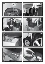
by opening the manual drain valve and check for condensate (

fig. 13

).

•  Periodical  service  inspection  of  the  air  receiver  is  needed,  as  internal 

corrosion  can  reduce  the  steel  wall  thickness  with  the  consequent  risk 

of  bursting.  Local  rules  need  to  be  respected,  if  applicable.  The  use  of 

the air receiver is forbidden once the wall thickness reaches the minimum 

value  as  indicated  in  the  service  manual  of  the  air  receiver  (part  of  the 

documentation delivered with the unit).

• Lifetime of the air receiver mainly depends on the working environment. 

Avoid installing the compressor in a dirty and corrosive environment, as 

this can reduce the vessel lifetime dramatically.

• Do not anchor the vessel or attached components directly to the ground 

or fixed structures. Fit the pressure vessel with vibration dampers to avoid 

possible fatigue failure caused by vibration of the vessel during use.

• Use the vessel within the pressure and temperature limits stated on the 

nameplate and the testing report.

•  No  alterations  must  be  made  to  this  vessel  by  welding,  drilling  or  other 

mechanical methods.

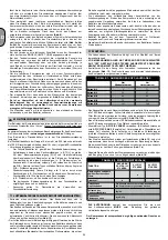
MAINTENANCE

4

• The service life of the machine depends on maintenance quality.

• 

PRIOR TO ANy OPERATION SET THE PRESSURE SWITCH TO THE 
OFF POSITION, PULL OUT THE PLUG AND COMPLETELy DRAIN THE 
RESERVOIR.

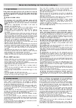
• Check  that  all  screws  (in  particular  those  of  the  head  of  the  unit)  are 

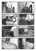
tightly drawn up (

fig. 10

). The check must be carried out prior to the first 

compressor starting.

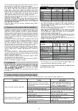
TABLE 1 – TIGHTENING OF HEAD TENSION RODS

Nm

Min. torque

Nm

Max. torque

Screw M6

9

11

Screw M8

22

27

Screw M10

45

55

Screw M12

76

93

Screw M14

121

148

• Clean the suction filter according to the type of environment and in any 

case at least every 100 hours. If necessary, replace the filter (a clogged 

filter impairs efficiency while an inefficient filter causes harsher wear on the 

compressor

 (figures 11a - 11b)

.

• Change  the  oil  after  the  first  100  hours  of  operation  and  subsequently 

every 300 hours. Check the oil level periodically.

• Use 

API CC/SC SAE 40

.  (For  cold  climates, 

API CC/SC SAE 20

  is 

recommended).  Never  mix  different  grade  oils.  If  the  oil  changes  color 

(whitish  =  presence  of  water;  dark  =  overheated),  it  is  good  practice  to 

replace the oil immediately.

• After topping up, tighten the plug (

fig. 12

) making sure that there are no 

leaks during use. Once a week, check the oil level to assure lubrication in 

time (

fig. 7a

).

• Periodically, check the tension of the belts which must have a flexion (f) of 

around 1 cm (

fig. 14

).

*

 Spent oil and condensate 

MUST BE DISPOSED OF

 in compliance with 

protection of the environment and current legislation.

The compressor must be disposed in conformity with the methods 
provided for by local regulations

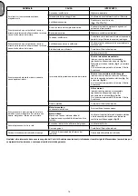
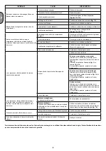
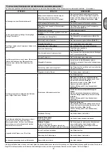
POSSIbLE FAULTS AND RELATED PERMITTED REMEDIES

5

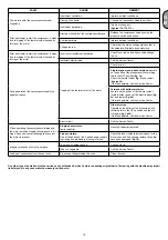
Request the assistance of a qualified electrician for operations on electric components (cables, motor, pressure switch, electric panel, etc).

TABLE 2 – MAINTENANCE

FUNCTION

AFTER THE 

FIRST 100 

HOURS

EVERy 100 

HOURS

EVERy 300 

HOURS

Cleaning of intake filter and/
or substitution of filtering 
element

Change of oil*

Tightening of head tension 
rods 

The check must be carried out prior to the first 

compressor starting.

Draining tank condensate 

Daily

Checking the tension of 
the belts 

Periodically

FAULT

CAUSE

REMEDy

Air leak from the valve of the pressure switch.

Check valve does not perform its function 

correctly due to wear or dirt on the seal.

Unscrew the hex-shaped head of the check 

valve, clean the housing and the special rubber 

disk (replace if worn). Re-assembler and tighten 

carefully (

igures 15a-15b

).

Condensate drainage cock open.

Close the Condensate drainage cock.

Rilsan hose not inserted correctly in pressure 

switch.

Insert the Rilsan hose correctly inside the 

pressure switch 

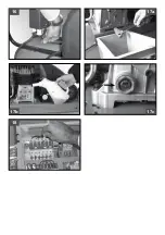
(ig. 16)

.

Reduction of eficiency, frequent start-up. Low 

pressure values.

Excessively high consumption.

Decrease the demand of compressed air.

Leaks from joints and/or pipes.

Change gaskets.

Clogging of the suction ilter.

Clean/replace the suction ilter 

(

igures 11a-11b

).

Slipping of the belt.

Check belt tension 

(ig. 14).

Summary of Contents for A39B/150 CM3

Page 1: ...150 3 4116024280 http kompressory vseinstrumenti ru remennye abac kompressor_abac_a39v_150_sm3_4116024280 http kompressory vseinstrumenti ru remennye abac kompressor_abac_a39v_150_sm3_4116024280 tab R...

Page 2: ...saanwijzing Brugsanvisning Instruktionsmanual K ytt ohjeet E Instrukcje obs ugi Upute za upotrebu Navodila za uporabo Kezel si tmutat P ru ka k obsluze N vod na obsluhu P Bruksanvisning Kullanma talim...

Page 3: ......

Page 4: ...376 57 1630 0207 00 A39B 8973 0376 57 1630 0207 00 NS12 8973 0376 57 1630 0207 00 NS12S 8973 0376 57 1630 0207 00 NS19 8973 0376 57 1630 0207 00 NS19S 8973 0376 57 1630 0207 00 PAT24 8973 0376 57 1630...

Page 5: ......

Page 6: ...2 4 3c 3a 3b 1b 5 1a...

Page 7: ...6c 7b 7a 6a ON OFF OFF ON 6b OFF ON 6d 8 9 OFF ON...

Page 8: ...11b 15a 14 12 10 13 11a 15b...

Page 9: ...17b 16 18 17a 17c...

Page 10: ...nainte de utilizare BG SRB Pre upotrebe pa ljivo pro itajte uputstva za upotrebu LT Prie imdamiesi darbo atid iai perskaitykite naudojimo vadov l EST Enne kasutamist lugege kasutamisjuhend t helepane...

Page 11: ...HR Pa nja elektri ni napon SLO Pozor elektri na napetost H Figyelem elektromos ram CZ Pozor elektrick nap t SK Pozor elektrick pr d RUS NO Forsiktig elektrisk str m TR Dikkat elektrik ak m RO Aten ie...

Page 12: ...brukning FIN Ottovirta GR PL Pr d Pobrany HR Absorbirana energija SLO Absorbirani elektri ni tok H Elnyelt ram CZ Spot eba el energie SK Pr dov spotreba RUS NO Str m Absorbert TR ekilen enerji RO Cure...

Page 13: ...iones del embalaje P Tamanho da embalagem NL Afmetingen verpakking DK Emballage m l S F rpackningens dimensioner FIN Pakkauksen mitat GR PL Wymiary opakowania HR Dimenzije omota SLO Dimenzije embala e...

Page 14: ...kabel H T pvezet k cs metszet CZ Pr m r nap jec ho kabelu SK Prierez nap jacieho k bla RUS NO Avdeling matekabel TR Besleme kablosu kesiti RO Sec iune cablu de alimentare BG SRB Presek napojnog kabla...

Page 15: ...enire manualmente premendo il pulsante di ripristino posto sulla scatola morsettiera del motore fig 2 Nelle versioni trifase sufficiente intervenire manualmente sul pulsante del pressostato riportando...

Page 16: ...MA DI QUALSIASI INTERVENTO COMMUTARE SU POSIzIONE OFF IL PRESSOSTATO DISINSERIRE LA SPINA E SVUOTARE COMPLETAMENTE IL SERBATOIO Controllare il serraggio di tutte le viti in particolare quelle della te...

Page 17: ...viare ig 1b Se l inconveniente persiste chiamare il Centro Assistenza Versioni con avviatore stella triangolo intervenire sul pulsante del termico collocato dentro la cassetta del quadro elettrico ig...

Page 18: ...tton of the thermal cutout inside the box of the electric panel figures 3a 3b 3c The single phase versions are fitted with a pressure switch equipped with a delayed closing air vent valve or with a va...

Page 19: ...ghtly drawn up fig 10 The check must be carried out prior to the first compressor starting TABLE 1 TIGHTENING OF HEAD TENSION RODS Nm Min torque Nm Max torque Screw M6 9 11 Screw M8 22 27 Screw M10 45...

Page 20: ...t ig 2 and restart igures 1b If the fault persists call the Service Center Versions with delta star starter operate on the button of the thermal cutout located inside the box of the electric panel ig...

Page 21: ...de courant Afin de faciliter le red marrage de l appareil en plus des op rations susmentionn es il est important d agir sur le bouton du pressostat en le ramenant en position de mise hors tension pui...

Page 22: ...caus par les vibrations du r servoir au cours de l utilisation Utiliser le r servoir dans les limites de pression et de temp rature sp cifi es sur la plaque signal tique et dans le rapport de tests C...

Page 23: ...nt dans la position de mise hors tension ig 1a R armer la protection thermique ig 2 et r armer ig 1b Si le probl me persiste contacter le Centre Apr s vente Versions avec d marreur toile triangle Inte...

Page 24: ...ngegebenen intermittierenden Verh ltnis so weist beispielsweise die kennzeichnung S3 50 auf 5 Minuten Arbeitszeit und 5 Minuten Stillstandszeit hin vorgesehen um eine berm ige Erhitzung des Elektromot...

Page 25: ...ltig zu lesen und zu beachten Ansonsten gelten f r Deutschland die Vorschriften der Druckbeh lterverordnung LUFTbEH LTER bEI bEH LTERMONTIERTEN EINHEITEN 3 Korrosion muss verhindert werden Das Kondens...

Page 26: ...sorkopf Den Vorderteil des Kompressors durch Bet tigen des Druckknopfs entleeren Geringe Temperatur Die Raumbedingungen verbessern Mangelnde Spannung Kontrollieren ob die Netzspannung den Kenndaten en...

Page 27: ...sobre el bot n del pres stato llev ndolo a la posici n de apagado y luego nuevamente a la de encendido fig 1a 1b En las versiones monof sicas hay que actuar manualmente apretando el bot n de restable...

Page 28: ...ntro de los l mites de presi n y temperatura indicados en la placa de datos y en el informe de prueba No se debe modificar este dep sito con procedimiento mec nico alguno ya sea soldando taladrando o...

Page 29: ...bot n del pres stato llev ndolo a la posici n de apagado ig 1a Rearmar la protecci n t rmica ig 2 y poner nuevamente en marcha ig 1b Si el inconveniente subsiste llamar el Centro de Asistencia Versio...

Page 30: ...o na posi o de desligado e depois de novo em ligado figs 1a 1b Nas vers es monof sicas necess rio intervir manualmente carregando no bot o de recupera o situado na caixa de bornes do motor fig 2 Nas v...

Page 31: ...A dura o da m quina est condicionada pela qualidade da manuten o ANTES DE QUALQUER INTERVEN O COMUTAR O MAN STATO PARA A POSI O OFF TIRAR A FICHA E ESVAzIAR COMPLETAMENTE O DEP SITO Controlar o aperto...

Page 32: ...hamar o Centro de Assist ncia Vers es com interruptor de arranque estrela tri ngulo carregar no bot o do dispositivo t rmico colocado dentro da caixa do quadro el ctrico ig 3c e reactivar ig 6d Se a a...

Page 33: ...mabsorptie Om het opnieuw opstarten van de machine te vereenvoudigen moeten niet alleen de beschreven handelingen worden uitgevoerd maar ook de drukknop op de pressostaat worden bediend deze moet eers...

Page 34: ...ukvat op trillingsdempers om mogelijke vermoeidheidsbreuken als gevolg van trilling van het vat tijdens het gebruik te voorkomen Gebruik het drukvat binnen de grenswaarden voor de druk en temperatuur...

Page 35: ...de thermische beveiliging ig 2 en start opnieuw ig 1b Als de storing blijft aanhouden contact opnemen met het Servicecentrum Versies met sterdriehoekaanzetter bedien de drukknop op de thermische bevei...

Page 36: ...n OFF og derefter over p positionen ON igen fig 1a 1b P enfase modellerne er det n dvendigt at gribe manuelt ind ved at trykke p nulstillingsknappen p motorens klembr t fig 2 P trefasemodellerne er de...

Page 37: ...ruernes opsp nding og i s rdeleshed dem p gruppens hoved fig 10 Kontrollen skal udf res inden den f rste start af kompressoren TABEL 1 FASTSP NDING TOPSTykkEBOLTE Nm Coppia Min Nm Coppia Min Bolt M6 9...

Page 38: ...en med trykrel ets knap ig 1a Genopret termomagnetsikringen ig 2 og start igen ig 1b Kontakt assistancecenteret hvis ulempen varer ved Modeller med stjerne trekantsstarter tryk p termomagnetens knap d...

Page 39: ...du trycka p knappen f r terst llning som sitter p motorns kopplingsdosa fig 2 P modeller av trefastyp r cker det med att trycka p tryckvaktens knapp s att den r i tillslaget l ge eller trycka p knapp...

Page 40: ...STICkkONTAkTEN DRAS UR OCH LUFTBEH LLAREN T MMAS FULLST NDIGT Kontrollera att alla skruvar r tdragna i synnerhet skruvarna p enhetens lock fig 10 innan kompressorn startas f r f rsta g ngen TABELL 1...

Page 41: ...get l ge ig 1a terst ll verhettningsskyddet ig 2 och terstarta ig 1b Om felet kvarst r kontakta serviceverkstaden Modeller med kontaktor stj rna triangel Tryck p knappen p verhettningsskyddet som sitt...

Page 42: ...men painaminen takaisin asentoon p ll riitt Vaihtoehtoisesti voi painaa s hk taulun rasiassa olevan l mp suojan painiketta kuvat 3a 3b 3c Yksivaihemalleissa on painekytkin jossa on moottorin k ynnisty...

Page 43: ...a ennen kompressorin ensimm ist k ynnistyst TAULUkkO 1 P DyN ANkkURITANkOJEN kIRIST MINEN Nm Minimimomentti Nm Maksimimomentti Pultti M6 9 11 Pultti M8 22 27 Pultti M10 45 55 Pultti M12 76 93 Pultti M...

Page 44: ...uudelleen kuvat 1b Jos vika ei poistu ota yhteytt Huoltokeskukseen Mallit joissa t htikolmiok ynnistys paina l mp suojan painiketta joka on s hk taulun rasian sis ll kuva 3c ja k ynnist uudestaan kuva...

Page 45: ...44 G R 1 4 20 dB 5 C 40 C 4 5 50 cm S3 50 5 5 1a 1b 2 3a 3b 3c 4 5 2 10 O 6a 6b 6c 6d tandem 7a 7b 6a 6b 6c 6d 11 bar 15 bar...

Page 46: ...bar 4 6a 6b 6c 6d 10 I ON tandem 8 9 3 13 4 OFF 10 1 Nm Nm M6 9 11 M8 22 27 M10 45 55 M12 76 93 M14 121 148 100 11a 11b 100 300 API CC SC SAE 40 API CC SC SAE 20 12 7a f 1 cm 14 2 100 100 300 24 h 24...

Page 47: ...46 G R 15a 15b rilsan rilsan 16 11a 11b 14 17a 17b 17c 1a 2 1b 3c 6d 1a 1b 18 5...

Page 48: ...i cie kiedy temperatura jest zbyt du a z powodu zbyt du ego poch aniania pr du W celu u atwienia ponownego uruchomienia maszyny wa ne jest poza podanymi operacjami zadzia a na przycisk presostatu usta...

Page 49: ...odzespo w bezpo rednio do pod o a ani do sta ych konstrukcji Zbiornik ci nieniowy nale y zamocowa na t umikach drga aby nie dopu ci do zm czenia materia u spowodowanego drganiami zbiornika Podczas u y...

Page 50: ...o w pozycji wy czony rys 1a Za o y ponownie protekcj termiczn rys 2 i ponownie uruchomi rys 1b Je li anomalia powt rzy si to zg osi si do Serwisu Technicznego Wersje z rozrusznikiem gwiazda tr jk t za...

Page 51: ...ela dovoljno je prekida mijenja a pritiska ru no staviti u poziciju UKLJU ENO ili aktivirati prekida termi kog dijela smje teno u kutiji elektri ne plo e slike 3a 3b 3c Jednofazni modeli su opremljeni...

Page 52: ...etanja kompresora TABLICA 1 PRITEZANJE KOMPRESORSKE GLAVE Minimalni moment sile Nm Nm Obrtni moment max Vijak M6 9 11 Vijak M8 22 27 Vijak M10 45 55 Vijak M12 76 93 Vijak M14 121 148 O istite usisni f...

Page 53: ...ika 1d Ako ne uklonite problem nazovite servisni centar Modeli sa starterom zvjezda trokut Pritisnite prekida termo za tite koji se nalazi u elektri nom razvodnom ormari u slika 3c i ponovno pokrenite...

Page 54: ...tno stikalo na priklju ni dozi motorja prikaz 2 Pri trifazni razli ici zado a ro no aktiviranje gumba tako da ga prestavite v polo aj vklju eno Za konec morate aktivirati temperaturno stikalo v notran...

Page 55: ...i kompresorske glave slika 10 Vijake morate preveriti preden prvi za enete kompresor TABELA 1 ZATEGOVANJE VIJAKOV KOMPRESORSKE GLAVE minimalni moment Nm maksimalni moment Nm Sornik vijak M6 9 11 Sorni...

Page 56: ...trikot Aktivirajte stikalo ki se nahaja v elektri ni stikalni omarici prikaz 3c in ga ponovno za enite prikaz 6d e je motnja e vedno prisotna pokli ite servisno slu bo Ostale razli ice Aktivirajte sti...

Page 57: ...jb li beind t s t fontos hogy a megadott m veleteken k v l vissza ll tsa a nyom skapcsol kapcsol j t a kikapcsolt helyzetbe s ut na jb l a bekapcsolt helyzetbe 1a 1b bra N h ny egy f zis t pus eset n...

Page 58: ...esztjelent sben megjel lt nyom s s h m rs kleti hat r rt kek k z tt haszn lja A tart lyon tilos hegeszt ssel f r ssal vagy m s mechanikai elj r sokkal v ltoztat sokat v gezni kARbANTART S 4 A g p lett...

Page 59: ...ok ll tsa vissza a nyom skapcsol kapcsol j t a kikapcsolt helyzetbe s ut na jb l a bekapcsolt helyzetbe 1 bra ll tsa helyre a h v delmet 2 bra s ind tsa be jra 1b bra Ha a kellemetlens g nem m lik el...

Page 60: ...dnof zov ch verz je pak t eba stisknout tla tko pro obnoven chodu kter se nach z na sk ni svorkovnice motoru obr 2 U t f zov ch verz sta ru n zapnout sp na presostatu anebo stisknout tla tko ochrann h...

Page 61: ...je nutn prov st p ed prvn m uveden m kompresoru do provozu TABULKA 1 UTAHOV N SVOREK HLAVICE Nm min utahovac moment Nm max utahovac moment roub M6 9 11 roub M8 22 27 roub M10 45 55 roub M12 76 93 rou...

Page 62: ...sor obr 1b Pokud probl m d l trv kontaktujte Technick servis Verze se zapojen m hv zda troj heln k Znovu zapn te ochrann sp na uvnit sk ky el rozv d e obr 3c a spus te kompresor obr 6d Pokud probl m d...

Page 63: ...h enie znovu spustenia strojn ho zariadenia je d le it okrem uveden ch oper ci manipulova s tla tkom presostatu uvies ho do polohy vypnut a potom znova do polohy zapnut obr 1a 1b Pri jednof zov ch ver...

Page 64: ...ho z vibr ci n dr e po as jej pou vania Pri pou van n dr e re pektujte limity teploty a tlaku ktor s uveden na dajovom t tku a v sk obnej spr ve Nevykon vajte iadne modiik cie na tejto n dr i prostred...

Page 65: ...o te do polohy Zapnut obr 1a Znovu nastavte tepeln ochranu obr 2 a re tartujte obr 1b Ak porucha pretrv va zavolajte do Servisn ho strediska Verzie so sp a om hviezda trojuholn k Zasiahnite na tepeln...

Page 66: ...65 R U S 1 4 m 20 dB 5 C 40 C 4 5 50 S3 50 5 5 1a 1b 2 3a 3b 3c 4 5 2 10 O 6a 6b 6c 6d Tandem 7a 7b 6a 6b 6c 6d 11 15...

Page 67: ...66 R U S 2 4 6a 6b 6c 6d I ON Tandem 8 9 3 13 4 10 1 M6 9 11 M8 22 27 M10 45 55 M12 76 93 M14 121 148 100 11a 11b 100 300 API CC SC SAE 40 API CC SC SAE 20 12 7a f 1 14 2 100 100 300 24 h 24 h 24 h...

Page 68: ...67 R U S 15a 15b 16 11a 11b 14 17a 17b 17c 1a 2 1b 3c 6b 1a 1b 18 5...

Page 69: ...p tilbakestillingsknappen som er plassert p motorens klemskruebrett fig 2 I trefase modellene er det nok gripe inn manuelt p trykkbryterens knapp ved flytte den tilbake til p eller ved trykke p den te...

Page 70: ...1 STRAMMING AV HOLDER FOR MUNNSTykkET Nm Min moment Nm Maks moment Bolt M6 9 11 Bolt M8 22 27 Bolt M10 45 55 Bolt M12 76 93 Bolt M14 121 148 Rengj re innsugingsfilteret i forhold til hvordan arbeidsmi...

Page 71: ...kyttelsen ig 2 og sl kompressoren p p nytt ig 1b Hvis feilen fortsetter oppst kontakt teknisk assistanse Modeller med stjernetrekantstartere Trykk p den termiske bryterens knapp den beinner seg i el t...

Page 72: ...tusu zerinde bulunan d meye basarak manuel olarak m dahale etmek gerekir ek 2 fazl versiyonlar nda bas n l er d mesi zerinde manuel olarak i lem yaparak yan k konumuna getirmek veya elektrik panosu ku...

Page 73: ...ALTIN T m vidalar n zellikle gurup kafas n n s k oldu unu kontrol edin ek 10 Kontrol n kompres r n ilk al mas ndan nce yap lmas gerekmektedir TABLO 1 EK C KAFA KAYI I Nm Min Tork Nm Maks Tork Civata M...

Page 74: ...numa getirin r ek 2 Termik koruyucuyu yeniden etkin hale getirin ek 2 ve yeniden al t r n ek 1b E er hata devam ediyorsa Bak m Servisini a r n Y ld z gen starter versiyonlar Elektrik panosu kutusu i e...

Page 75: ...ui n afara opera iilor descrise mai sus este indicat ca prin ap sarea butonului de pe presostat s opri i compresorul definitiv i s l porni i l din nou vezi fig 1a 1b Pe modelele monofazate este necesa...

Page 76: ...Controla i str ngerea tuturor uruburilor mai ales a celor din capul ansamblului fig 10 Controlul trebuie s fie efectuat nainte de prima punere n func iune a compresorului TABEL 1 NCHIDEREA CAPURILOR T...

Page 77: ...a i la Centrul de Service pentru asisten Modelul cu dispozitiv de pornire stea triunghi ap sa i pe butonul dispozitivului termic de pe panoul de comand vezi ig 3c dup care porni i din nou motorul vezi...

Page 78: ...77 B G 1 4 20 dB 5 C 40 C 4 5 50 S3 50 5 5 1a 1b 2 figg 3a 3b 3c 4 5 2 10 OFF 6a 6b 6c 6d 7a 7b 6a 6b 6c 6d 11 15...

Page 79: ...2 4 6a 6b 6c 6d 10 I ON 8 9 3 13 4 OFF 10 1 Nm Nm M6 9 11 M8 22 27 M10 45 55 M12 76 93 M14 121 148 100 11a 11b 100 300 API CC SC SAE 40 API CC SC SAE 20 12 7 f 1 14 5 2 100 100 300 24 h 24 h 24 h 15a...

Page 80: ...79 B G C C 11a 11b 14 17a 17b 17c 1a 2 1b 3c 6d 1a 1b 18...

Page 81: ...onda ponovno u polo aj UKLJU ENO slike 1a 1b Kod jednofaznih modela pritisnite dugme za resetiranje na priklju noj kutiji motora slika 2 Kod trofaznih modela dovoljno je pritisnuti prekida na tla noj...

Page 82: ...ZVUCITE UTIKA I U POTPUNOSTI ISPRAZNITE REZERVOAR Kontrolisati pritegnutost svakog zavrtnja a naro ito onih na glavi sklopa slika 10 Kontrola mora da se obavi pre prvog pokretanja kompresora TABLICA 1...

Page 83: ...toplotnog preoptere enja slika 2 a onda ponovno pokrenite kompresor slika 1b Ako ne uklonite problem nazovite servisni centar Modeli sa starterom zvezda trougao Pritisnite prekida toplotne za tite ko...

Page 84: ...uo perkaitimo be jau nurodyt operacij sl gio rel s mygtuk reikia perjungti pozicij OFF o po to v l ON ir i naujo jungti komprersori 1a 1b pav Vienfaziams kompresoriams reikia ranka paspausti mygtuk RE...

Page 85: ...ORO RESIVERIO Patikrinkite vis var t priver imo stiprum ypatingai galvut s dangtelio var tus 10 pav Atlikite visus patikrinimus prie paleid iant kompresori pirm kart 1 LENTEL GALVUT S TRAUKLI SUVER IM...

Page 86: ...2 pav ir v l paleisti 1b pav Jei gedimas kartojasi skam binti aptarnaujan ios mon s tarnyb Modelis su vaig d s trikampio starteriu paspausti temperat rin s rel s esan ios ele ktros skydo d ut s viduje...

Page 87: ...sissel litatud asendisse seej rel vajutada termonupule mis asub elektripaneeli karbi sisemuses figg 3a 3b 3c hefaasilist kompressorite puhul on normaalne et alustades pumpamist t hja paaki kostub m ne...

Page 88: ...eaegselt Soovitatavalt v hemalt iga 100 t tunni j rel Ummistunud hufilter p hjustab kompressori lekoormust ja kulumist Joon 11a 11b Vahetage li esmakordselt peale esimest 100 t tundi Regulaarne livahe...

Page 89: ...misel helistage Teeninduskeskusesse D y k ivituse puhul vajutage elektrikilbi sisse hendatud termoseadeldise nupule Joon 3c ning k ivitage kompressor Joon 6d Rikke kordumisel helistage Teeninduskeskus...

Page 90: ...rbas iek pus z m 3a 3b 3c Vienf zes versij ir spiediena relejs ar ventili kas izlai gaisu ja nokav jas aizv r an s vai ar ventili kur atrodas uz kontroles v rsta kas atvieglo motora palai anu t d ir...

Page 91: ...ts Skr ve M6 9 11 Skr ve M8 22 27 Skr ve M10 45 55 Skr ve M12 76 93 Skr ve M14 121 148 T r t ies k anas filtru emot v r apst k us bet vismaz jau katras 100 stundas Ja nepiecie ams nomain t aizs r jis...

Page 92: ...rtojas zvan t uz Pakalpojumu Centru Modelis ar delta tr sst ra starteri piespiest termoiek rtas pogu kas atrodas elektr bas nodal juma k rbas vid z m 3c un palaist v lreiz z m 6d Ja boj jums atk rtoja...

Page 93: ...92 Single phase Three phase Three phase...

Page 94: ......

Page 95: ......

Page 96: ......

Page 97: ...2236111771 00...

Reviews: