P. 24 - Chap. 4 Performance and specifi cations
G
B
4
Performance and
specifi cations
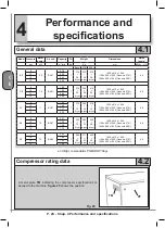
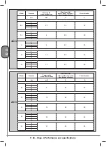
4.1
General data
-
Model Pressure Motor
power
Air end
Capacity Oil
Weight
Dimensions
Noise
levels*
bar
kW
m
3
/min
Kg
Kg
mm
dB(A) - L
p
(A)
Base 270 l 500 l
5.5
8
5.5
BA51
0.78
7
270
+
28
dryer
355
+
28
dryer
414
+
28
dryer
1030 x 615 x 1045
1180 x 600 x 1645 (Genesis 270 l.)
1960 x 600 x 1645 (Genesis 500 l.)
66
10
0.69
13
0.54
15
0.40
7.5
8
7.5
BA51
1.20
7
275
+
28
dryer
360
+
28
dryer
419
+
28
dryer
1030 x 615 x 1045
1180 x 600 x 1645 (Genesis 270 l.)
1960 x 600 x 1645 (Genesis 500 l.)
68
10
1.04
13
0.80
15
0.64
11
8
11
BA51
1.65
7
275
+
32
dryer
360
+
32
dryer
419
+
32
dryer
1030 x 615 x 1045
1180 x 600 x 1645 (Genesis 270 l.)
1960 x 600 x 1645 (Genesis 500 l.)
69
10
1.40
13
1.17
15
0.95
15
8
15
BA51
2.01
7
300
+
32
dryer
385
+
32
dryer
444
+
28
dryer
1030 x 615 x 1045
1180 x 600 x 1645 (Genesis 270 l.)
1960 x 600 x 1645 (Genesis 500 l.)
69
10
1.72
13
1.49
15
1.16
15
8
15
BA69
2.32
7
286
+
32
dryer
371
+
32
dryer
430
+
32
dryer
1030 x 615 x 1045
1180 x 600 x 1645 (Genesis 270 l.)
1960 x 600 x 1645 (Genesis 500 l.)
69
10
1.93
13
1.62
15
1.30
± 3 dB(A) to standards PNEUROP/Cagi
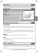
4.2
Compressor rating data
A metal plate
TM
indicating the compressor specifi cations is
applied to the machine:
fi gure 25
shows the position
Fig. 25
TM
PF
Summary of Contents for FORMULA Series
Page 1: ...GENESIS FORMULA MODULO 5 5 15 kW USE AND MAINTENANCE HANDBOOK GB ...
Page 2: ......
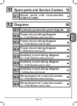
Page 82: ...P 80 Chap 12 Diagrams G B 12 Diagrams Hydraulic pneumatic plant diagram 12 1 ...
Page 85: ...P 83 Chap 12 Diagrams G B Power circuit wiring diagram 5 5 15 kW Machines with air dryer 12 3 ...
Page 86: ...P 84 Chap 12 Diagrams G B Power circuit wiring diagram 11 kW Machines with inverter 12 4 ...
Page 89: ...P 87 Chap 12 Diagrams G B Auxiliary circuit wiring diagram 11 kW Machines with inverter 12 7 ...


