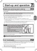
P. 36 - Chap. 7 Start-up and operation
G
B
Customization operating parameter
Programming of compressor operation on a daily or weekly basis
Programming and signalling of the Manufacturer’s maintenance schedule
Machine self-protection system to signal fault pre-alarms and automatically stop the machine in the
event of serious problems
Remote machine control
Possibility of connecting the compressor via CAN-BUS interface (optional) to other similar compressors
for integrated management of the set of machines
Remote compressor monitoring via personal computer and dedicated software (optional)
Fig. 34
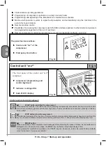
The panel has two sections:
Control unit “mc
2
” of the
compressor
Emergency stop button
7.2.1
Control unit “mc
2
“
Fig. 35
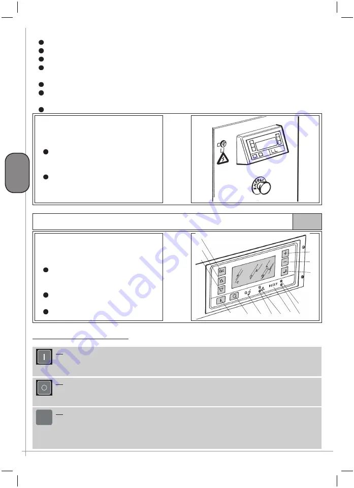
The
front panel of the control unit “mc
2
”
comprises:
compressor programming and
control keyboard
Indicator / setting LEDs
back-lit LCD display
K4
K5
K3
K6
K1
K2
K7
K8
K9
L1
L2
L3
L4
L5
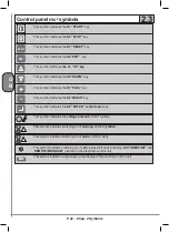
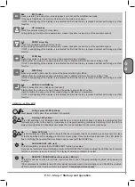
Control and programming keyboard
K1
START button (starting the compressor)
Used to start the machine. If remote control or programming (daily/weekly) are enabled, this key is used to enable
compressor functioning (priority control from keyboard). If alarm conditions have occurred, pressing of this key
has no effect
K2
STOP button (stop the compressor)
Permits timed stopping of the machine. If remote control or programming (daily/weekly) have been enabled, this
key can be used to disable compressor functioning (priority control). It does not operate at emergency level
K3
RESET button
Makes it possible to reset compressor fault messages after eliminating the causes of these. As the faults can be
displayed only in the main screen page, the RESET key is effective only during display of this.
During parameter modification operations, the RESET key can be used to restore the preset factory (default)
value for the type of compressor selected
RESET
Summary of Contents for FORMULA Series
Page 1: ...GENESIS FORMULA MODULO 5 5 15 kW USE AND MAINTENANCE HANDBOOK GB ...
Page 2: ......
Page 82: ...P 80 Chap 12 Diagrams G B 12 Diagrams Hydraulic pneumatic plant diagram 12 1 ...
Page 85: ...P 83 Chap 12 Diagrams G B Power circuit wiring diagram 5 5 15 kW Machines with air dryer 12 3 ...
Page 86: ...P 84 Chap 12 Diagrams G B Power circuit wiring diagram 11 kW Machines with inverter 12 4 ...
Page 89: ...P 87 Chap 12 Diagrams G B Auxiliary circuit wiring diagram 11 kW Machines with inverter 12 7 ...

