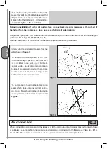
P. 37 - Chap. 7 Start-up and operation
G
B
K4
ESC button
Used to return to the main menu (previous level) or to cancel the modifications made.
If the key is held down, the control unit returns to the main screen page.
If OFF, back-lighting of the display is re-activated the first time the key is pressed without performing any other
function
ESC
K5
UP arrow key
Used for upward scrolling of menu items;
during setting of multiple-choice parameters. makes it possible to select one of the available options.
K6
DOWN arrow key
Used for downward scrolling of menu items;
during setting of multiple-choice parameters. makes it possible to select one of the available options.
If OFF, back-lighting of the display is re-activated the first time the key is pressed without performing any other
function
K7
PLUS key
Makes it possible to increase the value of the parameter being modified.
Starting from the main screen page, permits access to additional information and scrolling of this
If OFF, back-lighting of the display is re-activated the first time the key is pressed without performing any other
function
+
K8
MINUS key
Makes it possible to decrease the value of the parameter being modified
Starting from the main screen page, permits access to additional information and scrolling of this
If OFF, back-lighting of the display is re-activated the first time the key is pressed without performing any other
function
-
K9
ENTER / CONFIRM key
Used to access the menu displayed (next level).
Starting from the main screen page, makes it possible to access the menu tree.
Used to confirm the value or selection made during modification of a parameter.
If OFF, back-lighting of the display is re-activated the first time the key is pressed without performing any other
function
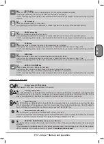
Indicator / setting LED
L1
Voltage present LED (yellow)
Must always be ON when the compressor is powered
L2
warning LED (yellow)
This LED switches on to indicate critical conditions or a minor fault that does not block the compressor; this
indication may refer to the need for maintenance or irregular operating conditions. Switching ON of this LED is
always accompanied by a descriptive message that can be displayed in the main screen page
L3
Alarm LED (red)
This LED switches on (steady light) to indicate that the compressor has been blocked by a serious fault; the type
of fault is described with a message in the main screen page. Once the fault has been reset, the LED starts to
flash, informing the operator that the situation can be reset with the RESET key
L4
AUTORESTART LED (red)
This LED switches on when the AUTORESTART function is enabled.
In the case of automatic restart following a blackout (AUTORESTART function enabled) the LED flashes to indicate
that the compressor is about to restart. The display shows the countdown to restart
L5
REMOTE / PROGRAM functions active LED (red)
This LED switches on when the remote control function or one of the programming functions (daily-weekly) is
enabled.
If the compressor is installed in line with other similar compressors and communication on a CAN-BUS is enabled,
LED L5 assumes other functions. Refer to chapter 8 “
Compressors in sequence
”
Summary of Contents for FORMULA Series
Page 1: ...GENESIS FORMULA MODULO 5 5 15 kW USE AND MAINTENANCE HANDBOOK GB ...
Page 2: ......
Page 82: ...P 80 Chap 12 Diagrams G B 12 Diagrams Hydraulic pneumatic plant diagram 12 1 ...
Page 85: ...P 83 Chap 12 Diagrams G B Power circuit wiring diagram 5 5 15 kW Machines with air dryer 12 3 ...
Page 86: ...P 84 Chap 12 Diagrams G B Power circuit wiring diagram 11 kW Machines with inverter 12 4 ...
Page 89: ...P 87 Chap 12 Diagrams G B Auxiliary circuit wiring diagram 11 kW Machines with inverter 12 7 ...

