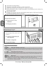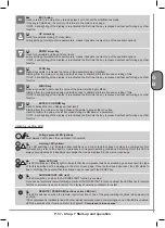
P. 41 - Chap. 7 Start-up and operation
G
B
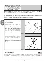
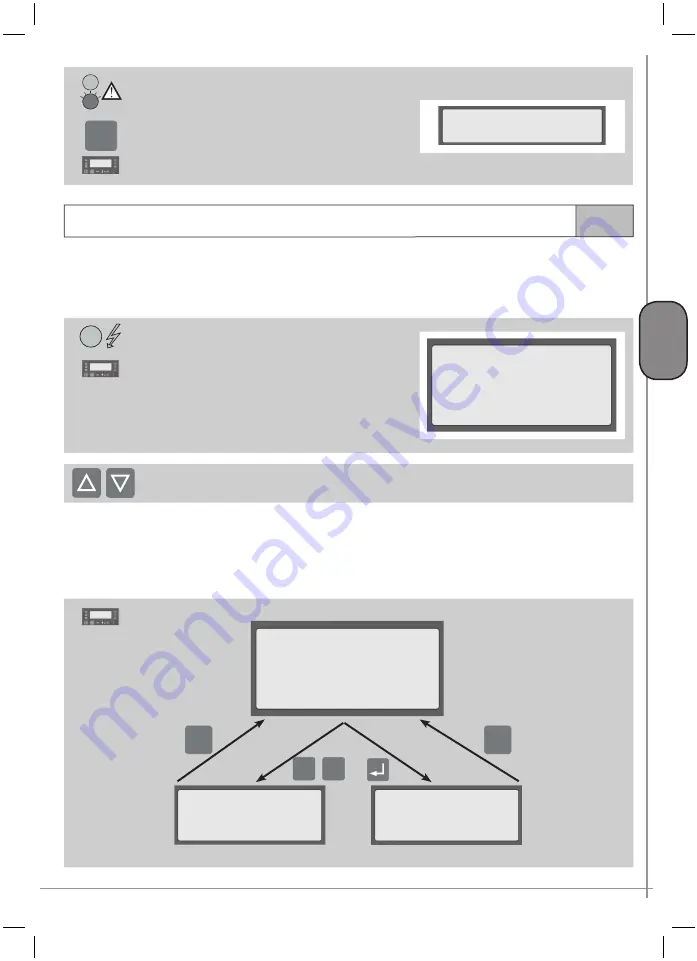
The emergency stop button is intercepted by the
monitoring unit which displays the following message
with LED L3 on
To reset,
release the EMERGENCY STOP button lock
and press button K3-RESET
12
EMERGENCY STOP
compress.-Block
RESET
7.4
Parameter configuration - menu tree
The machine was configured at the plant during testing;
the end user, however, can change some operating
parameters to customize machine performance to the specific applications.
Other parameter changes cannot be made Customer but only by Authorized Service Centre skilled
personnel.
The main screen page is displayed as follows:
LINE 1
net pressure
LINE 2
compression temperature of air-oil mixture
LINE 3
messages about operating conditions
LINE 4
hour and date, informations menu access,
tree menu access, quick language change
message
13
Pressure XX.X bar
Temperature XXX °C
Ready for start
10:40 DOM 25/05/2003
To change the language, use the
K5
and
K6 keys
After 60 seconds from pressing of the last key, the display is set to a
low level of brightness
.
The first time a key is pressed (excluding the K1-START, K2-STOP, K3-RESET control keys),
high level
brightness
of the display is restored while subsequent pressing of the keys produces the associated
function.
14
ESC
ESC
+ -
ADDIZIONAL
INFORMATIONS
MENU
TREE
7.4.1
7.4.2
Pressure XX.X bar
Temperature XXX °C
Ready for start
10:40 DOM 25/05/2003
b
) to
MENU TREE
using the K9 (ENTER) key
This menu permits access to all compressor
control and programming functions; the
main screen page is redisplayed using
the
K4-ESC
key or automatically after
60 seconds
a
) to
ADDIZIONAL INFORMATIONS
using the K7 (PLUS) and K8 (MINUS)
keys
This menu permits fast access to significant
information without having to enter the
menu tree; the main screen page is
redisplayed using the
K4-ESC
key or
automatically after 60 seconds
From the main screen page, it is possible to access:
14
Summary of Contents for FORMULA Series
Page 1: ...GENESIS FORMULA MODULO 5 5 15 kW USE AND MAINTENANCE HANDBOOK GB ...
Page 2: ......
Page 82: ...P 80 Chap 12 Diagrams G B 12 Diagrams Hydraulic pneumatic plant diagram 12 1 ...
Page 85: ...P 83 Chap 12 Diagrams G B Power circuit wiring diagram 5 5 15 kW Machines with air dryer 12 3 ...
Page 86: ...P 84 Chap 12 Diagrams G B Power circuit wiring diagram 11 kW Machines with inverter 12 4 ...
Page 89: ...P 87 Chap 12 Diagrams G B Auxiliary circuit wiring diagram 11 kW Machines with inverter 12 7 ...


