P. 65 - Chap. 9 Troubleshooting
G
B
V-F
V-V
Indication
Possible cause
Intervention
X
X
L2
flashing
DI
indicates:
“
Compression temp.
High.
”
Excessive ambient or air
recirculation temperature
Improve air exchange and
check installation requirements
X
X
FO
clogged
Replace
FO
(rif. par. 10.6)
X
X
FD
clogged
Replace
FD
(see. par. 10.6)
X
X
L2
flashing
DI
indicates:
“
Dewpoint probe error
”
Problems in the dew
temperature sensor
or its
connection
Call
Customer
Service Centre
9.6
The machine stops when it is running and warning
LED comes on
V-F
V-V
Indication
Possible cause
Intervention
X
X
L3 constant ON
DI
indicates:
“
Emergency
stop compress. - block
”
The
PE
button has been
pressed
Reset the
PE
button
(see. par. 7.2.2)
X
X
L3 constant ON
DI
indicates:
“
Net pressure
too high - block
”
VA
or solenoid valve problems
Call
Customer
Service Centre
Net pressure too high caused
by other compressors
Check working pressure of all
compressors
X
X
L3 constant ON
DI
indicates:
“
Compress.
motor overload - block
”
Low voltage
Check
voltage
X
X
Underscaled
power cables
Check installation
requirements
X
X
Critical functioning
temperature conditions
(high ambient temperature, hot
air recirculation)
Check functioning conditions
X
X
FD
clogged
Replace
FD
(see. par. 10.6)
X
X
FA
clogged
Replace
FA
(see. par. 10.4)
X
Star delta sequence
problems
Call
Customer
Service Centre
X
Motor thermal protection
problems
Call
Customer
Service Centre
X
X
Electrical motor
problems
Call
Customer
Service Centre
X
X
L3 constant ON
DI
indicates:
“
Line voltage
cutoff - block
”
Line voltage cutoff
problems
Check
line voltage
X
X
L3 constant ON
DI
indicates:
“
Compression temp
too high - block
”
Oil cooling low
Check functioning of the
electric fan and its fuses
FU3
.
Call
Customer
Service Centre
Summary of Contents for FORMULA Series
Page 1: ...GENESIS FORMULA MODULO 5 5 15 kW USE AND MAINTENANCE HANDBOOK GB ...
Page 2: ......
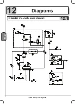
Page 82: ...P 80 Chap 12 Diagrams G B 12 Diagrams Hydraulic pneumatic plant diagram 12 1 ...
Page 85: ...P 83 Chap 12 Diagrams G B Power circuit wiring diagram 5 5 15 kW Machines with air dryer 12 3 ...
Page 86: ...P 84 Chap 12 Diagrams G B Power circuit wiring diagram 11 kW Machines with inverter 12 4 ...
Page 89: ...P 87 Chap 12 Diagrams G B Auxiliary circuit wiring diagram 11 kW Machines with inverter 12 7 ...


