Pag. 16
G
B
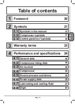
27
Clearance requirements
and system layouts
4.9
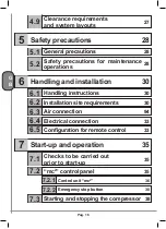
Safety precautions
28
5
28
General precautions
5.1
28
Safety precautions for maintenance
operations
5.2
Handling and installation
30
6
30
Handling instructions
6.1
30
Installation site requirements
6.2
94
Air connection
6.3
33
Electrical connection
6.4
33
Configuration for remote control
6.5
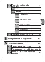
Start-up and operation
35
7
35
Checks to be carried out
prior to start-up
7.1
35
“mc
2
” control panel
7.2
36
Control unit “mc
2
”
7.2.1
38
Emergency stop button
7.2.2
38
Starting and stopping the compressor
7.3
Summary of Contents for GENESIS Series
Page 1: ...GENESIS FORMULA MODULO 5 5 15 kW USE AND MAINTENANCE HANDBOOK GB...
Page 2: ......
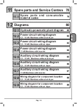
Page 82: ...P 80 Chap 12 Diagrams G B 12 Diagrams Hydraulic pneumatic plant diagram 12 1...
Page 85: ...P 83 Chap 12 Diagrams G B Power circuit wiring diagram 5 5 15 kW Machines with air dryer 12 3...
Page 86: ...P 84 Chap 12 Diagrams G B Power circuit wiring diagram 11 kW Machines with inverter 12 4...
Page 89: ...P 87 Chap 12 Diagrams G B Auxiliary circuit wiring diagram 11 kW Machines with inverter 12 7...


