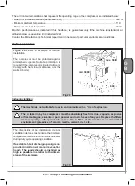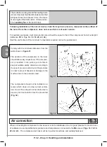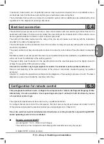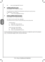
P. 22 - Chap. 2 Symbols
G
B
2.3
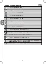
Control panel mc
2
symbols
This symbol indicates the
K1
“START”
key
This symbol indicates the
K2 “STOP”
key
This symbol indicates the
K3 “RESET”
key
RESET
This symbol indicates the
K4”EXIT”
key
ESC
This symbol indicates
the
K6
“UP” key
This symbol indicates the
K6”DOWN”
key
This symbol indicates the
K7”PLUS”
key
+
This symbol indicates the
K8”MINUS”
key
-
This symbol indicates the
K9 “ENTER” confirmation
key
T
his symbol indicates the
voltage present
LED
L1
(yellow)
Th
is symbol indicates switching on of
warning
LED
L2 (yellow)
This symbol indicates switching on of
alarm
LED
L3
(red)
This symbol indicates switching on of LEDs
L4
and
L5
(red) indicating “
AUTORESTART
” and
“
REMOTE/PROGRAM
” located on the electronic control unit
This symbol indicates a message on the display of the electronic control unit
Summary of Contents for GENESIS Series
Page 1: ...GENESIS FORMULA MODULO 5 5 15 kW USE AND MAINTENANCE HANDBOOK GB...
Page 2: ......
Page 82: ...P 80 Chap 12 Diagrams G B 12 Diagrams Hydraulic pneumatic plant diagram 12 1...
Page 85: ...P 83 Chap 12 Diagrams G B Power circuit wiring diagram 5 5 15 kW Machines with air dryer 12 3...
Page 86: ...P 84 Chap 12 Diagrams G B Power circuit wiring diagram 11 kW Machines with inverter 12 4...
Page 89: ...P 87 Chap 12 Diagrams G B Auxiliary circuit wiring diagram 11 kW Machines with inverter 12 7...


