P. 34 - Chap. 6 Handling and installation
G
B
38
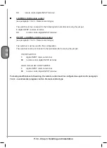
remote control digital INPUT terminal
LOAD/NO-LOAD remote control
(see paragraph 7.4.2.3 - Remote control type)
The switch must be connected to the following terminals after removing the jumper:
3
digital INPUT common terminal
38
remote control digital INPUT terminal
ON/OFF - LOAD/NO-LOAD remote control
(see paragraph 7.4.2.3 - Remote control type)
Two switches must be used for this configuration.
The switches must be connected to the terminals after removing the jumper:
ON/OFF SWITCH
3
digital INPUT common terminal
38
remote control digital INPUT terminal
LOAD / NO-LOAD START SWITCH
3
digital INPUT common terminal
39
remote control digital INPUT terminal
Following modifications to the wiring, the remote control must be configured as explained in paragraph
7.4.2.3 - Local/remote /program control - Remote control type
Summary of Contents for GENESIS Series
Page 1: ...GENESIS FORMULA MODULO 5 5 15 kW USE AND MAINTENANCE HANDBOOK GB...
Page 2: ......
Page 82: ...P 80 Chap 12 Diagrams G B 12 Diagrams Hydraulic pneumatic plant diagram 12 1...
Page 85: ...P 83 Chap 12 Diagrams G B Power circuit wiring diagram 5 5 15 kW Machines with air dryer 12 3...
Page 86: ...P 84 Chap 12 Diagrams G B Power circuit wiring diagram 11 kW Machines with inverter 12 4...
Page 89: ...P 87 Chap 12 Diagrams G B Auxiliary circuit wiring diagram 11 kW Machines with inverter 12 7...

