background image

22

Step 2:

 Connect the air compressor supply to the equipment. Then, 

turn the Pressure Vessel knob to “Open” position to let the vacuum 
pressure accumulate into the system (figure 2.1).

Figure 2.1

Step 3: 

Check that the air 

pressure gauge is between 6 
and 8 bar (figure 3.1).

 If not 

adjust the pressure by the 
regulator.

Figure 3.1

Air pressure 
regulator

Pressure gauge

Water trap

(If water is inside, 

drain it out in 

earlier stage)

Summary of Contents for SVL100

Page 1: ...E VACUUM LIFTER SVL100 ABACO MACHINES USA 14508 S Garfield Ave Paramount CA 90723 USA Tel 310 532 0366 Fax 310 532 0499 Email sales abacomachines com Website www abacomachines com ABACO MACHINES OPERATION MANUAL ...

Page 2: ......

Page 3: ...APPLICABLE MODEL of this STONE VACUUM LIFTER SVL100 OPERATION MANUAL ...

Page 4: ... List Suction cup left 9 5 Spare Part List Suction cup right 11 III Safety Instructions 15 1 General Warnings Cautions and Notes 15 2 Cautions for Operations 16 3 Instructions for Air Hose Assembly 18 4 Control System Overview 19 5 Device usage 21 IV Appendix 28 V Technical Problems Solutions 32 VI Inspection Maintenance 33 VII Warranty Policy 34 Warranty Certificate 35 ...

Page 5: ...eral safety precautions and instructions that must be understood and applied before during and after operations as well as maintenance to ensure personnel safety and protection of equipment Prior to performing any task the contents included in this manual should be reviewed and fully understood This manual highlights essential operating or maintenance procedure practice condition statement etc tha...

Page 6: ...1 ...

Page 7: ...Trolley stand Suction cup Vacuum tank Pneumatic cylinders Frame Control panel 2 ...

Page 8: ...gle Maintaining pressure of Pre vaccum tank SVL100 2200 lbs 1000 kg 308 lbs 140 kg 4 pcs 51 x 31 1320 x 800 mm 0 to 90 0 0 3 Compressed air source to be provided 6 to 8 kg cm bar 2 Length A inch mm Width B inch mm Height C inch mm 48 1230 55 1410 61 1565 1 Dimensions from 70 to 80 kPa ...

Page 9: ...4 2 Spare part list Overall ...

Page 10: ...7 SVL100 18 SVL100 19 SVL100 20 SVL100 1 2 SVL100 22 SVL100 24 SVL100 25 SVL100 26 SVL100 27 SVL100 28 SVL100 29 SVL100 30 U frame Suction cup left Allen bolt countersunk 20 M6 x Blind flange Bushing Cylinder pin 1 Pressure accumulator Stopper pin Screw M4 x 25 Pin 1 Spring Base with valve stopper pin Screw M4x10 Slide pipe Controller holder Lock nut M6 Grip handle Lifter positioning handle Pad 1 ...

Page 11: ...Swivel plate 1 SVL100 41 41 Cylinder pin 2 2 SVL100 42 42 Cap rubber 6 SVL100 43 43 Traverse beam 1 1 SVL100 44 44 Suction cup right 2 SVL100 45 45 Traverse beam 2 2 SVL100 46 46 Screw M6 x 10 4 SVL100 47 47 Washer 12 Ø 2 SVL100 48 48 Allen bolt M12 x 60 2 SVL100 49 49 Allen bolt M6 x 12 4 SVL100 50 50 Circlip 14 Ø 4 SVL100 51 1 SVL100 32 Pin 2 51 Brass washer 20 x 28 x 0 5 Ø Ø 1 SVL100 52 52 3 31...

Page 12: ...3 Spare part list Trolley stand 7 ...

Page 13: ...L 100 23 9 01 01 01 02 06 12 01 01 04 Bolt M10x20 Spring washer 10 Ø 04 04 SVL 100 23 10 SVL 100 23 11 01 02 03 04 05 06 07 08 09 10 11 12 13 14 15 Allen bolt M8x60 Bar 4 Washer brass 20 Ø Wheel 04 01 04 02 SVL 100 23 12 SVL 100 23 13 SVL 100 23 14 SVL 0 10 23 15 16 Circlip 20 Ø 04 SVL 100 33 17 Allen bolt M8 x 65 02 SVL 100 23 17 18 Cap rubber 05 SVL 100 23 18 P OS DESCRIPTION Q TY PART NUMBER ...

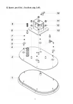
Page 14: ...4 Spare part list Suction cup left 9 ...

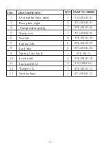
Page 15: ... Nut M6 Cap nut M6 Lock pin Spring lock knob Lock knob 1 4 1 1 6 6 6 1 4 1 3 4 5 6 7 8 9 10 11 12 Lock nut M12 Washer 12 Ø 4 1 SVL100 02 03 SVL100 1 02 0 SVL100 02 05 SVL100 02 04 SVL100 02 07 SVL100 02 06 SVL100 25 SVL100 02 08 SVL100 02 10 SVL100 02 11 SVL100 02 12 13 Suction base 1 SVL100 02 13 10 ...

Page 16: ...5 Spare part list Suction cup right 11 ...

Page 17: ...Ø Nut M6 Cap nut M6 Lock pin Spring lock knob Lock knob 1 4 1 1 6 6 6 1 4 1 3 4 5 6 7 8 9 10 11 12 Lock nut M12 Washer 12 Ø 4 1 SVL100 45 03 SVL100 1 45 0 SVL100 02 05 SVL100 02 04 SVL100 02 07 SVL100 02 06 SVL100 25 SVL100 02 08 SVL100 02 10 SVL100 02 11 SVL100 02 12 13 Suction base 1 SVL100 02 13 12 ...

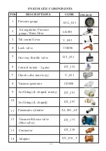
Page 18: ...MAGE CODE AVL_031 L 001 K V_042 V 006 H DT_252 6 Control switch 3 gates 7 8 9 10 11 Check valve one way Vacuum generator Air fittings L shaped rotary Air fittings L shaped Pneumatic cylinder DT_335 V_033 C 008 D DT_291 DT_297 XL 001_AT 13 12 Vacuum Release valve blue valve DT_177 13 Connector DT_230 14 Adaptor DT_230 _T PNEUMATIC COMPONENTS ...

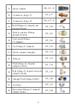
Page 19: ...DT_077 DT_077_N DT_250 DT_281 20 One touch fittings T shaped 22 23 24 Air fittings Y shaped Quick coupler straight Silencer Push fittings L shaped KQ2LF10 02 DT_283 DT_292 DT_319 DT_332 DT_334 25 Push fittings L shaped universal KQ2V10 02S DT_336 26 Straight Push fittings SMC DT_280 21 27 Air filter DT_323 28 One touch fittings L shaped KQ2L10 00 DT_288 14 ...

Page 20: ...is worn out or damaged WARNING Use the appropriate model of the lifter for the job as determined by the weight of the slab to be lifted Do not exceed the allowance specified W L L for the lifter Refer to page 3 WARNING During operation all workers in the work environment must be cautious and ensuring they are standing and moving safely around the work area to avoid unexpected accident injury WARNIN...

Page 21: ...tances Caution Inspections and maintenance should only be performed by well qualified persons a Before Operations Check the air system to ensure there is no signs of air leakages breakages or failures in the hoses Check the suction cups for any damage so that if there is damage fixit orchange Ensure the suction cups are clean and clear of dust grease or any othersubstanceswhich couldlead toimproper...

Page 22: ...n immediately when any abnormal sign any of deformation air leakage source pressure of less than 6 bar etc or noises occur Ensure that the weight of the slab being lifted is within the allowance specified Working Load Limit Refer to page 3 The operator is responsible for ensuring the work area is clear of obstacles and makes appropriate precautions observations and take appropriate actions to prev...

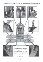
Page 23: ...Figure 1 2 18 Assemble the component accordingly connect the hoses in accordance with the given mating numbers ...

Page 24: ...19 Figure 1 3 4 CONTROL SYSTEM OVERVIEW ...

Page 25: ...pper nut to adjust speed controller 3 Tilt Control lever 0 90 4 Positioning handle extension Lock Unlock 6 Vaccum Release valve 7 Turn knob Open Close Open Vacuum generator operative 20 Figure 1 4 5 Lifter positioning handle Lifter positioning handle 5 6 Stopper pin 1 2 3 4 7 ...

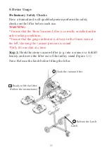
Page 26: ...alified person perform the safety checks on the lifter before each use WARNING Ensure that the Stone Vacuum Lifter is correctly installed and in safe working conditions Ensure that the gauge indicator is always in the Green zone at the left showing the vacuum pressure is sound Only lift one slab at a time 5 Device Usage Figure 1 1 1 Hook the vacuum lifter 2 Release the Latch Latch 3 Ready to lift t...

Page 27: ...osition to let the vacuum pressure accumulateintothesystem figure2 1 Figure 2 1 Step 3 Check that the air pressure gauge is between 6 and 8 bar figure 3 1 If not adjust the pressure by the regulator Figure 3 1 Air pressure regulator Pressure gauge Water trap If water is inside drain it out in earlier stage ...

Page 28: ...ce of the suction cups to be suitable for the slab s dimension figure 4 2 by pulling up the lock knob and moving the suction cups Note To adjust the angle of the suction cups refer to the Appendix at page 28 If the suction cups are in vertical upright position lean the control lever refer to page 28 to make suction cups horizontal If the tilting speed is too slow or too fast adjust the speed by th...

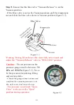
Page 29: ...um Warning During lift and move the stone slab never touch and adjust the Vacuum Release valve to RELEASE position Caution The air pressure on the pressure gauge must be between 70 kPa 80 kPa and figure 5 2 Never let the pressure drop during lifting and moving slabs Check the gauge time to time and confirm the vacuum pressure is in the safe zone and in each step The pressure vessel knob Open Close...

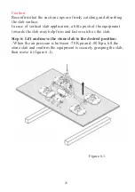
Page 30: ...cal slab application a little push of the equipment towards the slab may help firm and faster catch os the slab Step 6 Lift and move the stone slab to the desired position When the air pressure is between 70 Kpa and 80 Kpa lift the stone slab and confirm the equipment is securely grasping the slab then move it figure 6 1 ...

Page 31: ...26 Step 7 Place the stone slab at the desired postion figure 7 1 Figure 7 1 ...

Page 32: ...Figure 8 1 Figure 8 2 Figure 8 3 27 Stopper pin ...

Page 33: ...gle of suction cups from 0 to 90 o o Lean the tilt control lever to 90 to tilt the suction cups from 0 to o 90 and reverse o IV APPENDIX 28 Hold the Lifter positioning handle by hand firmly Pull the tilt control lever towards 90 o For reset the angle push the lever towards 0 o To adjust the speed of tilt refer to the figure 4 1 page 23 ...

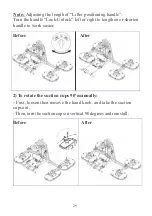
Page 34: ...le Turn the handle Lock Unlock left or right to lengthen or shorten handle to work easier 2 To rotate the suction cups 90 manually o First loosen then remove the hand knob and take the suction cupsout Then turn thesuctioncupsinvertical 90degreesandreinstall Before After ...

Page 35: ...re to the equipment 30 4 To clean the air filter Push the lock bracket down and rotate to open the cover 1 2 Use the compressed air gun to spray all dust on the filter Caution Do not use water or any solvent to clean the filter After the air filter has been checked and cleaned reassemble it as the location of origin Note It must be installed according to the correct direction of the valve Lock bra...

Page 36: ...etrochemicals to clean Mind the rubber not to scratch and to damage Caution 3 Sometimes any foreign object may clog the check one way valve In those cases fix the problem in the following manner 4 After confirming that no dust or any foreign object inside then carefully reassembly the check valve back together Tighten the screws little by little diagonally to fit the faces firmly Check valve is a ...

Page 37: ...ted leaks Then repair or replace the tube or device Pneumatic cylinder slips while lifting and adjusting the angle Inspect the piping by using diluted neutral soapy water to find suspected leaks Then repair or replace the tube or device Damaged pipes air leaks in pipes and valves Air pressure is less than 6 bar 3 Technical problem 4 Difficult to rotate the stone slab 90o the loading is within the ...

Page 38: ... as they may reduce rubber pads effectiveness and cause them to loss their vacuum Operator is recommended to always keep necessary spare parts on hand for immediate maintenance or repair purposes before operating Operator is responsible to ensure all parts are genuine parts from the manufacture and they are designed specifically for to be installing to this equipment Operator is responsible to ens...

Page 39: ...red We provide a on the one 1 year warranty Stone Vacuum Lifter SVL100 fromthedateof purchase During warranty period we will provide the replacement parts at no charge Please note shipping and handling fees may apply Warranty coverage is void if The operator failed to comply with the instructions in the manual The specifications are not followed Damage is due to inadequate maintenance and inspecti...

Page 40: ...roduct after purchase and or caused by negligence from the content ofthismanual In an event the equipment failed to operate and or required technical support operator user is responsible for reaching out to our Customer Support Department One of our team member will inform you operator user of the appropriate procedures on how to file warranty claim and advise you to your nearest approvedservice c...

Page 41: ......

Page 42: ......

Page 43: ...All Right Reserved J19 ...

Page 44: ......

Reviews: