background image

UM062 – PCIe490 User Manual 


r1.1 


UM062


            www.abaco.com 


- 7 - 


3  Electrical specifications 


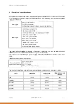
Input power is 100-240VAC and is supplied through the IEC60320 C14 connector on the rear 
of the chassis. The power supply is rated for 750W. The following table shows the power 
supply specifications. 

AC input 

Voltage 100-240 Vac 

Frequency 50-60Hz 

Current max 12A @ 100Vac, max-6 A @ 240Vac


DC input


+3.3V, max. current 22A 

+5V, max. current 22A 

+3.3V and +5V, max. combined power 120W 

+12V, max. current 62A 

+12V, max. power 744W 

-12V, max. current 0.3A 

-12V, max. power 3.6W 

+5VSB, max. current 2.5A 

+5V, max. power 12.5W 

Combined peak power 750W 


The power supply provides 4 auxiliary PCIe power connectors that can be used to source 
additional current to add-in cards that have high-power demands. 

The nominal electrical load per power supply rail of the PCIE490 are shown in the table 
below.  

Table 2: Nominal power consumption 

Nominal (only PCIe 

expansion card installed)


+3.3V, current 200mA 
+5V, current 2.5A 
+12V1, no current 
+12V2, current 1.1A (cooling fans)


The maximum electrical load per power supply rail per expansion slot is shown in table  

Slot 

Slot Rail 

Supply rail 

Max current  per 

slot (A) 

1-8


+3.3V 

+3.3V 

6A 

1 and 3


+12V 

+12V1 

5.5A 

2 and 4


+12V 

+12V1 

2.1A 

5 and 7


+12V 

+12V2 

5.5A 

6 and 8


+12V 

+12V2 

2.1A 


Summary of Contents for 4DSP PCIe490

Page 1: ...1 PCIe490 PCIexpress expansion chassis User Manual Abaco Systems USA Support Portal This document is the property of Abaco Systems and may not be copied nor communicated to a third party without the written permission of Abaco Systems Abaco Systems 2016 ...

Page 2: ... UM062 www abaco com 2 REVISION HISTORY Document Revision Changes Author Peer Review Quality Approval Date r1 0 Initial Release EBA IVK IVK 07 13 2016 r1 1 Added standard power cord delivery information to 1 3 IVK EBA JDS 11 28 2016 ...

Page 3: ...d related documents 4 1 1 Acronyms 4 1 2 Related Documents 4 1 3 Requirements and handling instructions 4 2 Product Overview 5 2 1 Chassis Description 5 2 2 PCIe host card and 6 2 3 System overview 6 3 Electrical specifications 7 4 Maintenance 9 5 Environment 9 6 Ordering information 9 ...

Page 4: ...ipheral Component Interconnect PCIe PCI Express Table 1 Glossary 1 2 Related Documents PCI Express Card Electromechanical Specification Revision 2 0 PCI Express 225W 300W High Power Card Electromechanical Specification Revision 1 0 1 3 Requirements and handling instructions The PCIE490 must be equipped with boards compliant to the PCI Express Card Electromechanical Specification Revision 2 0 Obser...

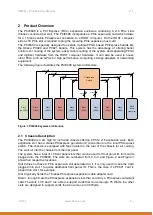
Page 5: ...sion PCIexpress Switch 4 lanes 4 lanes 4 lanes 4 lanes 4 lanes 4 lanes 16 lanes 4 lanes 4 lanes Figure 1 PCIE490 system architecture 2 1 Chassis Description The PCIE490 is a 4U high 19 inch wide chassis offering 8 PCIe x16 expansion slots Each expansion slot has a 4lanes PCIexpress generation 2 connections to the local PCIexpress switch The chassis is equipped with fans located in the rear of the ...

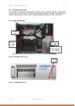
Page 6: ...t card The PCIe x16 host card has to be installed in the host computer system The 16 lanes expansion cable is then connected between the two x16 PCIe host cards 2 3 System overview 0 1 2 3 4 5 6 7 8 9 ATX power supply PCIe expansion cable adapter Cooling fans Expansion x16 PCIe slots Figure 2 PCIE490 internal view 0 1 2 3 4 5 6 7 8 9 ON OFF Switch Figure 3 PCIE490 front view ...

Page 7: ...wer 3 6W 5VSB max current 2 5A 5V max power 12 5W Combined peak power 750W The power supply provides 4 auxiliary PCIe power connectors that can be used to source additional current to add in cards that have high power demands The nominal electrical load per power supply rail of the PCIE490 are shown in the table below Table 2 Nominal power consumption Nominal only PCIe expansion card installed 3 3...

Page 8: ...requirements when plugging a PC821 into the system Place a PC821 only in slot 1 3 5 or 7 Always connect the auxiliary power connector to the PC821 The system can hold a maximum of 8 PC820 boards The PC820 can be plugged into all slots and requires the auxiliary power connector to be connected when fitted into slot 2 4 6 or 8 ...

Page 9: ...ndom N A Shock N A 6 Ordering information PCIE490 A E0 E1 E2 E3 E4 E5 E6 E7 E8 C9 Environmental A 5 C to 50 C Slot 0 F slot ocupied by FMC attached to the back of card in next slot E Empty Slot 1 P 4DSP PC821 card Q 4DSP PC820 card X other thirdparty PCIe card E Empty Slot 3 Same as slot1 Slot 4 Same as slot2 Slot 9 C PCIe link cable card Slot 8 Same as slot2 or C PCIe link cable card Slot 7 Same ...

Reviews: