background image

28  CR11*, CP11*, CT11* 6U CompactPCI® SBC 

Publication No. HRMCR11 Rev. B.0 

CPCI 

connector reference 

The CPCI specification nwnber

the CPCI connectors from bottom to top JI

J2, J3, J4, and JS. The CPCI connectors on the 

CR! 

I are J700!, 

J7002, J7003, 

J7004, and J7005 respec

ti

vel

y. 

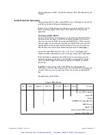
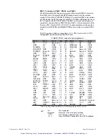
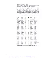
Table 6:  Signal name groups 

Signal groups 

Hard disk controller si

gn

als 

SAT A interface signals 

COM!, COM2 signals 

VGA signals 

Universal Serial Bus 

DVI signals 

LAN signals 

Audio interface 

SMB (I2C-Bus) 

IPMI 

General purpose I/0 

JTAG debugport 

Misc

signals 

PMC IO Signals 

NC: 

Determiner 

PHD 

.... 

and \PHD 

.... 

SATA 

.. 

CL 

.. 

,

C

.

.

.

. . 

VI...

V2 

.. . 

USB 

.. 

TX ... 

,

HOTPLG 

LPA 

LPB 

.. , 

M

l..

.

M2,,, 

AU 

.. 

SMB 

.. . 

IPMI ... , ICMB ... 

GPIO 

.. 

TDI, TDO

TMS, TCK 

\

SPEAKER 

\RST_BUT 

VBATIN 

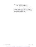
PMC ... 

not connected 

Artisan Technology Group - Quality Instrumentation ... Guaranteed | (888) 88-SOURCE | www.artisantg.com

Summary of Contents for CR11 Series

Page 1: ...service in house repair center WE BUY USED EQUIPMENT Sell your excess underutilized and idle used equipment We also offer credit for buy backs and trade ins www artisantg com WeBuyEquipment REMOTE IN...

Page 2: ...Hardware Reference Manual CR11 CP11 CT11 6U CompactPCI SBC Publication No HRMCR11 Rev B 0 Artisan Technology Group Quality Instrumentation Guaranteed 888 88 SOURCE www artisantg com...

Page 3: ...proved Producer Compliance Scheme PCS and subject to suitable contractual arrangements being in place will ensure WEEE is processed in accordance with the requirements of the WEEE Directive Abaco Syst...

Page 4: ...distributed via the Abaco website You may register for access to manuals via the website LINKS https www abaco com products cr11 https www abaco com products cp11 https www abaco com products ct11 Th...

Page 5: ...cate it a unique Case number for use in any future correspondence Alternatively you may also contact Abaco s Technical Support via LINK support abaco com Returns If you need to return a product there...

Page 6: ...4 describes how to get started Chapter 5 describes aEI onboard and panel interfaces with pin assignments Chapter 6 contains notes on system resources Chapter 7 lists details of the function blocks Ch...

Page 7: ...o low transition Text in Courier font indicates a command entry or output from an Abaco embedded PC product using the built in character set Notes warning symbols and cautions call attention to essent...

Page 8: ...quest Options This manual describes the basic product plus all optio11s Your product may 11ot have all optio11s i mpleme11ted Please verify with your purchase co11tract which opti 011s are i mpleme11t...

Page 9: ...I Single Board Computer All three boards are based on the same PCB design These thre e products will be referred to in this manual as the CR I family Any further specification in this document referri...

Page 10: ...mputer can only offer with several add on cards Extensionboards canbe cowiected via the CPCI CompactPCI interface The minimized board size and the large number ofinterfaces and functions allow the CR...

Page 11: ...B iliU l ll 41 _ t i CE IK US8 0 2 1 IU J J USII J I SMBus temperatures IETH100 5PD user EEPROM factory EP I 6700PXH LAN 571EB P64 564 1111 t O HPCI Term CPCI Bridge PCI Tc 1111 1232 485 Driver1 O f i...

Page 12: ...module Keyboard Mouse Via USB port LCDNGA ATI M22 graphics controller with 32 MB DDR2 memory dual head display with maxinmm resolution 1280 x I024 analog and DVI USB Two front and two rear USB 2 0 por...

Page 13: ...The I 0 signals are available at the re ar com1ectors The high speed PMCI will be available as an XMC slot as soon as its specification is finalized CPCI System slot Up to 7 peripherl slots 64 Bit CPC...

Page 14: ...apter 4 in the Interfaces section for wore details The list of styles available is shown below Table I Styles available CR I 2 3 4 6 8 X X X X X Front panel Extended temperature X X X X Parts soldered...

Page 15: ...will verify proper operation after shipping and before the product is integrated into your system Please check that the delivered package contains the following items Table 2 Delivery volume Qty Item...

Page 16: ...ace upon which you place the unprotected CR I should be static safe usually facilitated by the use ofantistatic ma ts From the tin1e the board is removed from the antista ticbag lllltil it is in the c...

Page 17: ...e to the following Please read this manual carefully before w1packing the module or fitting it into your system This will certainly save tin1e and avoid trouble Observe all precautions for electrostat...

Page 18: ...term reliability When w1packing the board and whenever handling it thereafter be sure to hold the board by the front panel or the card ejectors as shown in the drawing on the left Do not hold the boa...

Page 19: ...fully See also additional advisories for VMEbus and CompactPCI products below Cow1ect all IO cables Once you are certain that all modules are correctly fitted into the system and all com1ections have...

Page 20: ...this feature requires that Hot Swap functions are also available on the backplane See Hot Swap for details Initially you way plug the CR I into your 6U system slot ofyour CPCI system Optionally when...

Page 21: ...need an external adaptor to be fully compatible with the VGA standard connector and pin outs On the transition module you either can cow1ect a DVI panel or a standard VGA Monitor but not both a t the...

Page 22: ...lized You may also press the DELETE key when the LED goes from blinking orange to blinking green Consult the AMI BIOS for CR I CPII CTII User s and Progranuner s Manual for further information on how...

Page 23: ...ct voltage levels on 3 3 V and 5 V Ifyou ever see the board not starting well or doing resets at random states please check the voltage ofthe three supply voltages at the baclq lane When 111easuring t...

Page 24: ...repeated then this beeps are issued within the BIOS execution to show some other failures i e fails in memory detection or if no VGA is detected For more information please check theAMIBI0S8 CheckPoi...

Page 25: ...oard DEL key at the right moment Especially when using a slow starting monitor it might be too late to wait for the CRT to show the message Press DEL to enter Setup Better look for the LED and press D...

Page 26: ...he necessary drivers So do not expect the blue LED to go on and offaccording to the CPCI specification if no driver is loaded Whenever the CR I unexpectedly issues a reset and starts booting again you...

Page 27: ...h section on a particular interface includes a graphics illustration ofthe cow1ector and a pin assignment table as well as notes on certain signal line characteristics if necessary For interfaces ofth...

Page 28: ...Single slot fr ont panel This drawing indicates the location ofinterfaces on the front panel ofthe CPII dual slot board f 00 OOOOi f OO OOOOi Figure 8 Dual and single slot fr ont panels This chapter d...

Page 29: ...roups Signal groups Hard disk controller signals SATA interface signals COM COM2 signals VGA signals Universal Serial Bus DVI signals LAN signals Audio interface SMB I2C Bus IPMI General purpose I 0 J...

Page 30: ...A B C D E F 25 REQ64 ENUM Gt ID 24 5V LVIO b Gt ID 23 AD04 AD03 GND 22 GND L 3 3V 3 3V ADOO L 5V AD06 GND 21 AD09 ADOS M66EN Gt ID 20 GND VIOb ADll GND 19 ADIS AD14 GND GND 18 GND 3 3V PAR SV ACK64 AD...

Page 31: ...PMCII0_36 GND 5 PMCII0_45 PMCII0_44 PMCII0_43 PMCII0_42 PMCII0_41 GND 4 PMCII0_50 PMCII0_49 PMCII0_48 PMCII0_47 PMCII0_46 GND 3 PMCII0_55 PMCII0_54 PMCII0_53 PMCII0_52 PMCII0_51 GND 2 PMCII0_60 PMCII0...

Page 32: ...8 PMC2I0 57 PMC2I0 6 Git ID PMC2VIO PMC2I0_64 PMC2I0_63 PMC2I0_62 PMC2I0_61 Git ID Cl_DCMXD Cl_DSR IXD IPHO_CSO IPHO_IOR IPHO_IOW Git ID Cl_RXDIRTS Cl_RTSIRTS PHO_AO PHO_D08 PHO_D07 Git ID Cl TXD CTS...

Page 33: ...HD_JOW GND 26 25 HD_IOR NC 28 27 HD_RDY GND 30 29 HD_DAK NC 32 31 HD_IRQ ATA detect 34 33 HD_Al HD_A2 36 35 HD_AO HD_CSJ 38 37 HD_CSO GND 40 39 DASP 42 41 5V 5V NC 44 43 GND Gigabit Ethernet Interfac...

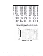
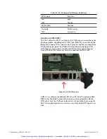
Page 34: ...tivity ofthe interfaces Table 11 Ethernet LED display definitions LEDi green On Off LED2 yellow On blink Off Ftu1ction Link No link Ftu1ction Tx Rx activity No activity The pin assignment at the rear...

Page 35: ...yout Table 12 Fast Ethernet connector pin assignments U5102 2 3 4 5 6 7 Name 10 iOObase TxD TxD RxD Not used Not used RxD Not used Not used 8 Two LED s LEDi green and LED2 yellow are integrated in the...

Page 36: ...support the RI Ring Indicator signal For RS422 485 usage this missing signal is the RxD negative receive data therefore this front panel com1ector does not work with RS422 485 Please use the rear com...

Page 37: ...to convert the RJ45 style RS232 without RI mechanic ally electrically to a Sub D9 connec tor see table below The pin assigmnent for this optional cable YLROISRS is shown below Table 15 RJ45 converter...

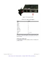
Page 38: ...12 15 9 5 6 7 8 10 4 11 the Fused 5 V pin is protected with a 2 A fuse For 11om1al operation don t exceed100 mA current The used fuse does automatically recover ifthe over current is resolved USB Int...

Page 39: ...cket outslCeview Figure 17 USB couuedor layout Table 17 USB connector pin assignments Pl680 2 3 4 Pl681 2 3 4 the Fused 5 V pin is protec ted with a 2 A fuse For nom1al operation don t exceed 500 mA c...

Page 40: ...GND PUP AD63 11 12 3 3V AD62 PCICLK PCIRST AD61 13 14 GND GND 15 16 REQO AD59 17 18 V l 0 AD57 19 20 AD28 V l 0 21 22 PON PON GND AD29 AD26 GND AD60 AD58 GND AD56 AD25 AD55 23 24 3 3V AD54 GND AD53 2...

Page 41: ...C2 connedor pin assignments P7201 P7202 Pin Pin P7201 P7202 NC 01 02 12V NC GND 03 04 PCIIRQ6 NC PCIIRQ7 12V NC NC 05 06 PCIIRQ4 GND PRESENT GND 07 08 Reserved PCIIRQS Reserved 09 10 Reserved GND PUP...

Page 42: ...in I ofthe I 0 connector is PMCxIO_Ol Pin 2 is PMCxI0_02 and so on The x denotes PMCI or PMC2 respectively All traces are not connected to any signal onboard and no pairs or length adjusted traces are...

Page 43: ...able DRAM 00000 9FFFF SAOOOO SBFFFF SCOOOO SDFFFF SEOOOO SFFFFF I00000 3FFFFFFF 4000000 FFFBFFFF SFECOOOOO FFEFFFFF SFFFOOOOO SFFFFFFFF I MByte System RAM Video RAM if enabled Used by PCI ROMs VGA SCS...

Page 44: ...h Ox2E8h Ox2Efh Ox2F8h Ox2FFh Ox3E8h Ox3Efh Ox3F8h Ox3FFh DMA Controller I Interrupt Controller I Counter Timer Keyboard Controller NMI Status and Control Keyboard Controller RTC NMI Mask DMA Page reg...

Page 45: ...OM2b Real Time Clock Power Management Contr PnP PCI b PnP PCI b PS 2Mouse Numeric Coprocessor External IDE d Onboard IDE Parity Error ECC Error System Error This interrupt is available when no I11tem1...

Page 46: ...r the processor to run an interrupt acknowledge cycle Intenupt P1iority The priorityofinterrupts in the I 0 APIC is independent ofthe interrupt number For example interrupt 10 way be given a higher pr...

Page 47: ...ng feature and reduces the voltage and frequency dynamically Ifthis feature is active the CR I will indicate it with shortclicks at the speaker In case ofa catastrophic die overheating above 125 C the...

Page 48: ...The CR I supports also the Interrupt haudliugs with APIC Advanced Interrupt Controller This handling ofthe APIC interrupt services must be supported by the operating system The I 0 APIC handles intem1...

Page 49: ...n board The CRlI System BIOS automatically detects cow1ected EIDE SATA HDDs or flash disks and enters the corresponding drive parameters into the BIOS setup This fe ature allows faster and easier hand...

Page 50: ...or reduc e resolution to get a stable display of good quality This is especially in1porta11t for the highest resolution of 2048 x 1280 and 1600 x 1200 Software Installation The Technical Product Info...

Page 51: ...ied with the CTII includes the most commonly used software drivers and utilities The Ethernet controller 82571EB from Intel used with the CR I is a high perforniance dual Gigabit Ethernet 0 100 1000 M...

Page 52: ...PU Hot Extraction which means the CR I is removed from a live system as a non system CPU Hardware Connection Process Power Up Down of the CR I onboard voltages Software Cowiection Proc ess Cow1ection...

Page 53: ...implemented on the CR I board TI1e sensor is loc ated dose to the CPU and shows the die temperanue of the CPU and the local onboard temperature For programming information please see the AMI BIOS for...

Page 54: ...ease see the AMI BIOS for CR I CPII CTII User s and Progranuner s Manual For moreinfomiatiou about geographic addressing in appliance to system management see PICMG 2 9 GPIO 0 7 Eight GPIO Pi t1s are...

Page 55: ...ay be connected between the appropriate IO cow1ector at the back side and GND The PRST on J7002_C42 PICMG2 0 is used as Reset input only for the system board and is in this case compatible to the oubo...

Page 56: ...he exact values depend on model and style The CR I is RoHS compliant The following two tables are intended to help you calculate the power consumption ofa CR I system Select power consumption dependin...

Page 57: ...please add around IO TI1e Celeron CPU has one CPU core only estimated values Table 30 Power consumption DRA I dependent CRII BIOS POST during memory initialization DOS prompt or CPU running full cach...

Page 58: ...mated life time depending on temperature and power status The diagram below shows discharge ifboard is not powered from the system i e ifbattery has to supply all current for the clock circuits 16 0 1...

Page 59: ...y the system then the battery is not supplying power to the clock circuits However self discharge happens Typical self discharge rates are less than 0 3 percent per year with respect to a folly loaded...

Page 60: ...uld slide forward out ofthe holder Pressure can be alternated between the two sides to get the battery to slide out ofthe socket The battery should slide forward enough that it could be removed from t...

Page 61: ...es 6 8 High Temperature OS C Storage Operating See note Low Temperature 40 C Storage Operating 0 C 85 C 85 C See diagram on next page 40 C 40 C 55 C 40 C Temperature Shock 10 C min 20 C min 20 C min S...

Page 62: ...T7400 Core 20uo 2 16GHz 30 0 l 1 5 2 2 5 3 free Airspeed into Slot m s Figure 21 Temperature vs airspeed The above diagram is valid for a usage at heights up to 1000 Ill above sea level For higher he...

Page 63: ...required only if needed on the PMC slot Ifthis voltage appears too late in the startup cycle the HotSwap controller will not control the ramp up ofthe optional 12 V on startup In that case the 12 V i...

Page 64: ...s This specification is valid too for PMC modules used on the CR I Please note that some PMC mezzanine modules may not function when the CR I supply voltage is close to the lower margin of 3 3V 3 PICM...

Page 65: ...500 V peak against GND and any other supply voltage By itselfthe onboard digital grotmd GND and the front panel chassis frame ground FGND are isolated 011 the CR I with a layout distance of more than...

Page 66: ...ment Plan Component Side CR11 V1 i I s I le _ iD jod 0 0 1 II CR11 V1 Figure 22 CRH Vl component side placement plan a I 0 0 D DI llf a 0 o i i 0 0 t o a iDx o io o Artisan Technology Group Quality In...

Page 67: ...mpactPCI SBC Publication No HRMCR11 Rev B 0 Placement Plan Solder Side CR11 V1 CR11 V1 Figure 23 CRH Vl solder side placement plan Artisan Technology Group Quality Instrumentation Guaranteed 888 88 SO...

Page 68: ...ssary power switching To avoid this problem please use SATA disks instead TI1ey are physically hot swappable Please note You either c an use a DVI display on P4l00 or a standard VGA Monitor Display wh...

Page 69: ...1 CT11 6U CompactPCI SBC Publication No HRMCR11 Rev B 0 1 I ID CTM17 VO 1 R Figure 24 CTl 117 component locations 0 0 i Artisan Technology Group Quality Instrumentation Guaranteed 888 88 SOURCE www ar...

Page 70: ...ce is designed as a 40 pin 2 54 Will pitch wale cow1ec tor to fit directly to one or two extemal IDE hard drives The cable length must not exceed 30 cm It is reconunended to use an 80 pole high densit...

Page 71: ...GND 24 23 HD_IOW GND 26 25 HD_IOR NC 28 27 HD_RDY GND 30 29 HD_DAKO NC 32 31 HD_IRQ NC 34 33 HD_AI HD_A2 36 35 HD_AO HD_CS3 38 37 HD_CSJ GND 40 39 NC SATA Connectors P1600 P1601 and P1602 The SATA in...

Page 72: ...P2903 for all audio signals Ifthere is no onboard SATA HDD there are connectors 011 the front panel for headphone out line in and digital SPDIF out The headphone output and the line in are standard 3...

Page 73: ...IN_L LINE_IN_R 5 6 AGND NC 7 8 SPDIF_OUT GND 9 10 FUSE_VCC 5 V supplied by the CRII and fused with max 2 A at CTMI7 for normal operation don t exceed I00 mA at this pin Ethernet Interface 10 100 1000B...

Page 74: ...t connector pin assignments Name 10 IOObase TxD TxD RxD NC NC RxD NC NC Name IOOObase LP_DA LP_DA LP_DB LP_DC LP_DC LP_DB LP_DD LP DD Ethernet 2 2 3 4 5 6 7 8 Two LEDs LEDi green and LED2 yellow are i...

Page 75: ...l connector has only 8 pins It does not support the Ring Indicator Rl on RS232 and it does not support RS422 485 because it is missing RXD negative Receive Data RS422 485 is available only on rear cow...

Page 76: ...pliedby theCR I and fused with max2 A atCTM 17 for normal operation don t exceed 100 mA at this pin P2202 isDB9 P2200 P2201 are pin headers onCTMI7 Graphics interfaces TheCTM 17 offers an analog digit...

Page 77: ...l C2 C3 C4 cs 12345 76 _ 9 10 II 12 13 15 16 17 16 19 20 21 za 2324 1 3 Figul e 32 DVI connectol layout Table 44 DVI connectol digital pin assignment Signal name Pin Signal name 13 14 15 16 17 18 19 2...

Page 78: ...with two PMC slots Table 46 VGA connector pin assignment Name V2_RED V2_GREEN V2_BLUE V2_HSYNC V2_VSYNC GND DOC DATA DDC CLK P4200 2 4 6 8 10 I 3 5 7 9 11 12 13 USB connector P1680 P1681 Four channels...

Page 79: ...tery to CR I For a description please check the sectionExternalBattery hlput PMC 1 0 connectors P7101 P7102 The PMC I 0 signals ofboth PMC slots are available at 64 pin male headers P7101 P7102 The fo...

Page 80: ...eader Table 49 GPIO connectol pin assignment Name P2000 Name GPIOO 2 GPIOI GPI02 3 4 GPI03 GPI04 5 6 GPIOS GPI06 7 8 GPI07 GND 9 10 FUSE_VCC 5 V supplied by the CR I and fused with max 2 A at CTM17 Fo...

Page 81: ...RMCR11 Rev B 0 Placement Plan g CH m c J u o _ j J f icH qa t S o g ti oj rnrnrn D 01 1 Rn 00 Hi CTM17VO 0 q i o o Q flllel Figure 35 Placement Plan CTMl7 0 0 j Artisan Technology Group Quality Instru...

Page 82: ...0 Pins are connected to the rear IO cow1ector on the CR I as defined in the PICMG 2 3 specification A5 V key is mow1ted on PMC2 for 5 V compatible PMC cards A3 V key is mow1ted on PMC for 3 V compati...

Page 83: ...36 1 Iount Pl IC board to CRll Note The PCI specification defines 3 3 V with a margin of 0 3 V Some PMC mezzanine modules way not ftuiction when the supply voltage is dose to the lower margin of3 3 V...

Page 84: ...About This Manual 83 r screw M2 IOJ l nl Secornfory lhermal lnterfare Figure 37 i lounting of Secondary Thermal Interface on Pl IC module Artisan Technology Group Quality Instrumentation Guaranteed 8...

Page 85: ...e CR I offers dual core CPU teclU1ology with dual cha1U1el DRAM up to 4 GB It has an XMC PMC slot an additional Fast Ethernet port on the front two SATA cha1U1els two USB cow1ectors at the front panel...

Page 86: ...11 CR9J J5 COM1 J5 J5 COM2 J5 J5 EIDE J5 J5 PMC21 0 J5 J4 SATA1 PS 2 J4 J4 SATA2 LPT J4 J4 VGA2 Flooov J4 J4 USB 2 3 J4 J4 USB4 5 J4 J4 VGA1 J4 J4 DVl 1 J4 J4 ICMB J4 J4 GPIO J4 J4 Soeaker J4 J4 Reset...

Page 87: ...TATIONS OR WARRANTIES OF ANY KIND WHETHER EXPRESS OR IMPLIED INCLUDING BUT NOT LIMITED TO WARRANTIES OF DESIGN MERCHANTABILITY OR FITNESS FOR A PARTICULAR PURPOSE ALL OTHER LIABILITY ARISING FROM RELI...

Page 88: ...service in house repair center WE BUY USED EQUIPMENT Sell your excess underutilized and idle used equipment We also offer credit for buy backs and trade ins www artisantg com WeBuyEquipment REMOTE IN...

Reviews: