Publication No. HRMCR11 Rev. B.0
About This Manual 35
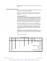
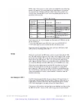
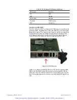
Table 13: Fast Ethernet LED display definitions
LEDi green
On
Off
LED2 yellow
On, blink
Off
Ftmction
Link
Nlo link
Ftmction
T:x/Rx activity
Nlo activity
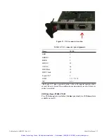
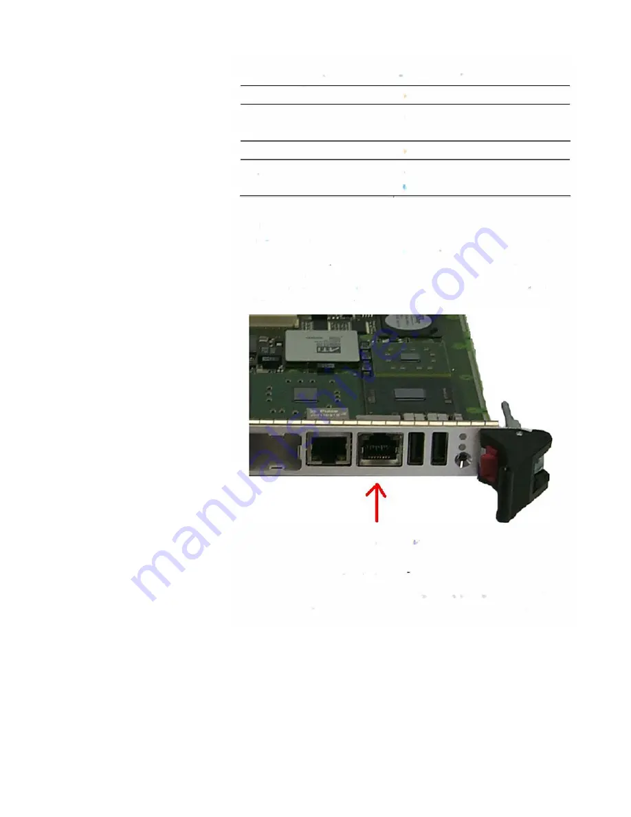
Serial Port COM1 P2201
The CRI I offers two RS232 serial ports
.
All COM ports are accessible via the
transition module, and additionally COM!
(
o
nl
y RS232) is accessible via the
front panel com1ector. This coimector has 8 pins only and does not support the
RI (Ring Indicator
)
signal. For RS42
2
/
4
85 usage this missing signal is the
RxD-
(
negative receive data
)
, therefore this front panel com1ector does not
work with RS4
22
/
48
5.
Please use the rear com1ections for RS4
22
/
48
5.
Figure 14: COl\11 location
COMI, 2 are software selectable for RS-232 or
R
S-42
2
/
485 operation within
BIOS se
tu
p
.
The RS485 output drivers can be enabled or disabled with the
DTR signal
.
An active DTR means the drivers to be enabled. When using the
RS422 setting the o
u
tp
u
t
drivers are always enabled and the DTR signal is not
u
s
e
d
.
Artisan Technology Group - Quality Instrumentation ... Guaranteed | (888) 88-SOURCE | www.artisantg.com

