68 CP9*, CR9*, CT9* Celeron M/Pentium M
Publication No. HRMCP9 Rev. B
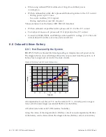
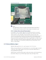
Figure 8-3 Battery Removal
NOTE
If exchanged by customer, please use same type for replacement and ensure correct polarization.
For operating without battery please check the following description of the external battery input.
8.8.3
Battery Removal and Replacement
Locate battery on the computer. Reference the product manual if it is not easily
located. On some of the dual slot SBCs, the top board may need to be removed to
make it easier to remove the battery. Once the battery is located, take a non-
conductive tool and push at the back of the battery holder. Gently apply pressure in
order to not break the socket. The battery should slide forward out of the holder.
Pressure can be alternated between the two sides to get the battery to slide out of the
socket. The battery should slide forward enough that it could be removed from the
socket. A new battery can be installed by sliding it into the holder. Make sure to
observe correct polarity.
8.9 External Battery Input
VBATIN input ranges 2.4 to 3.3 V, max. Current (@ 3.0 V; 35 °C) 5 µA
Without an onboard battery it is recommended to use an external supply connected
to this input. This voltage supplies the real time clock and the CMOS RAM for
storing the BIOS Setup settings.
Without battery and without this supply voltage, the real time clock oscillator has to
be started at each power up. This time gets longer when operating at lower


