Publication No. PPC11A-HRM/1
Functional Description 59
4.20.8 Real-Time Clock
The PPC11A provides a Maxim DS3231 real-time clock.
This device can be powered from the +5VSTDBY signal (
) when the main
power supply is removed (no battery is provided on-board).
4.20.9 Temperature Sensor
The PPC11A has an On Semiconductor NCT214 temperate sensor. This monitors the
temperature near the processor (giving an indication of the core temperature); it also
monitors the ambient temperature on the PCB. It is located in the area of highest
average PCB temperature.
The temperature sensor supports the range -40°C to +150°C or greater with an
accuracy of ±3 degrees or better. The readings are available to software.
4.20.10 Motion Sensor
The PPC11A has an STMicroelectronics LIS33HH motion sensor.
4.20.11 Power Manager
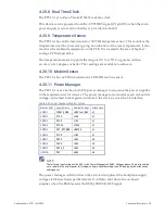
The PPC11A uses a Lattice L-ASC10 power manager to sequence the power supplies
in the required order for devices. The power manager also monitors each rail, and its
voltage can be read from registers internal to the device, across the I
2
C interface.
Table 4-30 Power Manager Monitor Points
Monitor Point Supply Name
Nominal Voltage Attenuation
VMON1
T2081_CORE
+0.9V to +1.05V x1
VMON2
P1V0
+1.0V
x1
VMON3
P1V2
+1.2V
x1
VMON4
P1V35
+1.35V
x1
VMON5
VCC_VTT_DDR +0.675V
x1
VMON6
P1V8
+1.8V
x1
VMON7
P2V5
+2.5V
x3
VMON8
P3V3
+3.3V
x3
VMON9
P3V3_2
+3.3V
x3
HVMON
P5V
+5.0V
x4
NOTE
The full-scale input voltage of the ADC in the Power Manager is 2.048V. Voltages above 2V are attenuated,
so to calculate the actual power rail voltage, software should multiply the ADC reading by the attenuation
setting above.
The power manager will shut down the on-board supplies if the backplane supply
voltages fall below their specified levels. It will also shut down the on-board
supplies when the BMM asserts the BMM_POWER_OFF signal.

