Publication No. PPC11A-HRM/1
Functional Description 49
4.18.3 XMCs
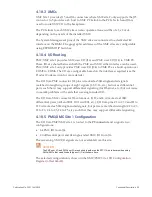
XMC Site 1 provides J15 and J16 connectors where XMC site 2 only supports the J25
connector. Jn5 provides a x8, host to XMC PCIe link to the PCIe Switch and J16 is
used to route XMC I/O to the backplane.
The PCIe links to each XMC site can also operate at lane widths of x1, x2 or x4,
depending on the needs of the installed XMC.
The System Management pins of the XMC sites are
connected to a dedicated I
2
C
interface on the BMM. The geographic addresses of the XMC sites are configurable
4.18.4 I/O Routing
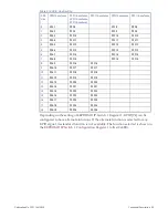
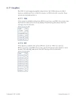
PMC/XMC site 1 provides XMC user I/O (J16) and PMC user I/O (J14) to VME P0.
These I/O are shared between both the PMC and XMC; either interface can be used.
PMC/XMC site 2 only provides PMC user I/O (J24) to VME P2 as a build option over
COM3 to COM6. The I/O are configurable based on the interfaces required (see the
The I/O from PMC connector J14 pins is tracked as 50Ω single-ended signals,
matched in length in groups of eight signals (1-8, 9-16, etc.) but not as differential
pairs such that it may support differential signaling (for Ethernet, etc.) but not cause
cross-talk problems with cards that use single-ended I/O.
The I/O from XMC connector J16 columns A, B, D, and E is tracked as 100Ω
differential pairs (A01 and B01, D01 and E01, etc.). I/O from pins C1 to C19 and F1 to
F19 is tracked as 50Ω single-ended signals, but pairs are matched in length (C2 to C3,
F2 to F3, C4 to C5, F4 to F5, etc.) such that they may support differential signaling.
4.18.5 PMC/XMC Site 1 Configuration
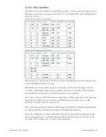
The I/O from PMC/XMC site 1 is routed to the
P0 connector
and supports two
configurations:
•
64 PMC I/O from J14
•
20 differential pairs and 24 single-ended XMC I/O from J16
The remaining XMC I/O signals are not available from this site.
CAUTION
The PMC user I/O and XMC user I/O are shorted together on the PPC11A, so take care when using
PMCs/XMCs that can drive both types of I/O at the same time.
The selected configuration is shown in the

