FMC30RF User Manual
r1.3
UM015
- 6 -
4.1 Phycisal specifications
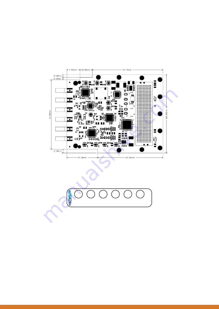
4.1.1 Board Dimensions
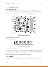
The FMC30RF card complies with the FMC standard known as ANSI/VITA 57.1. The card is
a single width conduction cooled mezzanine module (with region 1 and front panel I/O). A
front rib on the carrier hardware is not supported. The stacking height is 10mm.
AFE
7225
TRF
3720
TRF
3711
TRF
3765
CDCE
62005
AMC
7823
REF IN
REF OUT
RF IN
RF I/O
TX CLK
RX CLK
Figure 2: FMC30RF dimensions
4.1.2 Front panel coax inputs
The FMC30RF can be ordered with MMCX or SSMC connector type. Six connectors are
available on the front panel.
TX
CLK
RF
I/
O
RF
IN
RX
CLK
REF
OUT
REF
IN
Figure 3: FMC30RF bezel layout
4.2 Electrical specifications
The FMC30RF card uses a mix of LVDS and LVCMOS signals. According to the FMC standard
VADJ should be +2.5V to support LVDS, but the FMC30RF is designed to accept any level on
VADJ ranging between 1.65V and 5.5V. VIO_B_M2C connections are connected to VADJ on
the FMC30RF. Level translators are implemented to guarantee VADJ level on the FMC
connector for all single ended communication and control signals.
4.2.1 EEPROM
The FMC30RF card carries a 2Kbit EEPROM (24LC02B) which is accessible from the carrier
card through the I
2
C bus. The EEPROM is powered by 3P3VAUX. The standby current is only

