24 VMICPCI-7055/CPCI-7055RC Hardware Reference Manual
Publication No. 500-657055-000 Rev. G
1.6 Installation
The VMICPCI-7055/CPCI-7055RC conform to the CompactPCI physical
specification for a 6U board. The VMICPCI-7055/CPCI-7055RC can be used for
system control or as a peripheral board. It can be plugged directly into any
standard chassis accepting either type of board. The following pictures illustrate
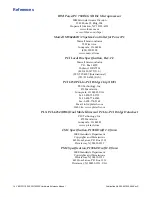
the symbols used to identify the slots in a standard CompactPCI chassis.
The following steps describe the recommended method for installation and
powerup of the VMICPCI-7055/CPCI-7055RC:
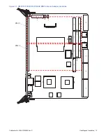
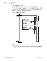
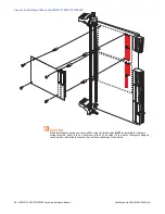
1. If a PMC is to be used, install it on the VMICPCI-7055/CPCI-7055RC prior to
board installation (as shown in Figure 1-5 on page 26). Refer to the Product
Manual for the PMC module for configuration and setup.
2. The VMICPCI-7055/CPCI-7055RC must be installed in a designated slot of
the CompactPCI backplane (see symbols above for selection of the correct
slot).
NOTE
Air flow as measured at the output side of heatsink is to be greater than 400LFM.
3. Insert the VMICPCI-7055/CPCI-7055RC into a CompactPCI chassis system
controller or peripheral slot. While ensuring that the board is properly
aligned and oriented in the supporting board guides, slide the board
smoothly forward against the mating connector. Use the ejector handles to
firmly seat the board.
4. All needed peripherals can be accessed from the front panel or the rear I/O
VMIACC-7055/ACC-7055RC RTMs. Each connector is clearly labeled on the
front panel, and detailed pinouts are in Appendix A.
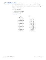
5. Connect an RS232 terminal to COM0 (see
).
This symbol identifies the
This symbol identifies
System Controller slot
peripheral slots
This symbol identifies
Dual LAN Node slots


