background image


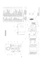
KEY COMPONENT DESCRIPTIONS

1. First Stage Filter. 1” Coarse/Particulate Pre-filter (P/N: F621). 

6. Filter Access Door. 

2. Second Stage Filter. 2” Pleated Particulate Pre-filter (P/N: H502).  7. Control Panel. 
3. Alternate Second Stage Filter. 2” High Capacity Carbon Filter 
   (P/N: VL1002). 

8. Rubber Feet. 
9. Plastic Guides. 

4. Final Stage Filter. 99.97% HEPA filter (P/N: H16166-99). 

10. Door Latch. 

5. Motorized Impeller. 

11. Exhaust outlet – 10” nominal diameter. 


OPERATING THE UNIT 


BEFORE OPERATING THE UNIT 

Inspect and tighten any HEPA filter retaining bolts that may have loosened during transportation. Inspect the 
filters for any material or structural damage prior to use and replace any damaged filters before operating the 
unit.  When removing any filters prior to operation, always put them back in place with the airflow indicator on 
the filter housing oriented in the proper direction (if applicable). 
 
As with any air filtration system, external airflow losses not attributable to the air filtration unit will reduce the 
airflow of the system. The following recommendations can minimize airflow losses created by external static 
resistance. 

1.  Always use the minimum length of ducting possible with the fewest possible number of turns and bends. 
2.  Rigid  metal  ducting  creates  less  turbulence  and  consequently  less  airflow  loss  than  flexible  ducting. 

Regardless of the type of ducting used, rigid, “sweep-type’, radiused connections should be used for all 
turns and bends. 

3.  If flexible ducting is used, it must be kept as taut as possible to avoid flattening. 


MODES OF OPERATION 

1. 

Negative Pressure

 – used to help ensure that airborne contaminants do not escape from a contained area 

by maintaining negative (lower) air pressure within that area compared to adjacent areas. Any air leakage 
will be an inflow of external air, not an outflow of contaminated air. To ensure that the proper pressure 
differential is maintained, the volume of HEPA-filtered air exhausted from the containment area must be 
the greater of 10% or 100 CFM higher than the volume of air entering. This pressure differential can be 
established by: 

a.  placing the unit inside the containment area and using it to push air out of the containment area. 

Attach flex duct at the outlet collar and exhaust the HEPA-filtered air outside of the containment 
area according to regulations – outdoors or another location within the building. 

b.  placing the unit outside of containment area and using it to pull air out of the area. Attach flex duct 

between the inlet collar and the containment area. 

2. 

Recirculation

 – used to reduce concentrations of airborne contaminants in a room or area by continuously 

cleaning the air and exhausting it back into the same room or area. 

3. 

Positive  Pressure

 – used to help prevent airborne contaminants from entering a containment area by 

maintaining positive (higher) pressure within that area compared to adjacent areas. Any air leakage will be 
an  outflow  of  clean  air,  not  an  inflow  of  external  air.  To  ensure  that  the  proper  pressure  differential  is 
maintained, the volume of HEPA-filtered air supplied to the area must be the greater of 10% or 100 CFM 
higher than the volume of air exhausted. This pressure differential can be established by: 

a.  placing the unit inside the containment area and using it to pull air into the containment area. 

Attach flex duct between the inlet collar and a location outside of the containment area. 

b.  placing the unit outside of containment area and using it to push HEPA-filtered air into the area. 

Attach flex duct at the outlet collar and exhaust the HEPA-filtered air inside of the containment 
area. 

 
If the room air filtration units are being used to create and maintain a negative/positive pressure condition, the 
pressure  differential  between  the  negative/positive  room  and  the  environment  outside  the  room  should  be 

Summary of Contents for HEPA-AIRE PAS600

Page 1: ...04 20 HEPA AIRE Portable Air Scrubber PAS600 Instruction Manual Abatement Technologies Inc Abatement Technologies Inc Georgia USA 800 634 9091 Abatement Technologies Limited Ontario Canada 905 871 4720 www abatement com ...

Page 2: ... published by the Occupational Safety and Health Administration Centers for Disease Control and Prevention Environmental Protection Agency American Society of Heating Refrigerating and Air Conditioning Engineers and all other federal state provincial and local regulations TABLE OF CONTENTS Safety Instructions 1 Requirements For Safe Operation 1 Important Safety Instructions 1 General Information 2...

Page 3: ...cal equipment always make sure that the unit is turned OFF prior to connecting the power cord to an electrical outlet or disconnecting it from an electrical outlet Failure to do so will cause arcing and could result in personal injury fire hazards and or damage to the unit Do not disconnect the power cord from supply receptacle while the unit is operating Warning To reduce risk of electrical shock...

Page 4: ...ble of filtering many airborne contaminants An alternate carbon pre filter for capturing low concentrations of odors vapors gases and volatile organic compounds collectively known as OVG is also available Types of contaminants captured by particulate pre filters HEPA filter or carbon filters Dirt Lung damaging particles Low concentrations of OVG Dust Metal fumes Low concentrations of Volatile Orga...

Page 5: ...shment of any more accurate rule of thumb than one s sense of smell Since off gassing of adsorbed OVG can occur when the adsorption capacity of the filter is reached replace the carbon filter as soon as odor breakthrough is sensed More detailed information on carbon adsorption can be found in an article titled Activated Carbon How Is It Used How Does It Work which can be found on the Abatement Tec...

Page 6: ...k to ensure that any circuit to which the unit is connected is protected by a 15 amp circuit breaker The unit itself is equipped with a 12 amp circuit breaker 5 The units should be connected to a three prong properly grounded electrical outlet equipped with a Ground Fault Circuit Interrupt GFCI device A GFCI is an electrical safety device that will trip the circuit and stop the flow of electricity...

Page 7: ...f contaminated air To ensure that the proper pressure differential is maintained the volume of HEPA filtered air exhausted from the containment area must be the greater of 10 or 100 CFM higher than the volume of air entering This pressure differential can be established by a placing the unit inside the containment area and using it to push air out of the containment area Attach flex duct at the ou...

Page 8: ...is 8 amp limit Note If the equipment connected to the GFCI receptacle draws more than a total of 8 amps the circuit breaker on the control panel and or the building breaker will trip This condition can be remedied only by reducing the total amperage draw DAISY CHAINING Daisy Chaining refers to the operation of multiple units on one circuit with only one of the units plugged into a 120 V 15 A elect...

Page 9: ...Technologies cannot recommend the type of PPE required as that will need to be determined by safety risk assessment personnel based on various risk factors including the type of particulates being captured by the air filtration device and the surrounding environment where the units are being used transported or serviced Note Filters being replaced must be disposed of in accordance with federal sta...

Page 10: ...N after changing the first stage filter the second stage filter should be replaced Changing the Second Stage Filter 1 With the unit operating turn the latches on the pre filter access door counter clockwise and open the door 2 Open the pre filter access door 3 Remove the second stage filter by lifting it up until the bottom clears the filter door cavity Tilt the bottom of the pleated filter out an...

Page 11: ...estart motorized impeller that will restart without warning after a temporary power interruption or recovery from a thermal overload over heating condition Keep clear of the motorized impeller at all times to reduce the risk of injury Occasionally a defective component will cause the unit to operate improperly or not at all Any electrical component can fail Refer to the Wiring Diagrams and Wiring ...

Page 12: ...tacked Pre filter access Swing out hinged door secured in place with cam latch First stage pre filter 1 deep coarse particulate pre filter P N F621 Second stage pre filter 2 deep pleated particulate pre filter P N H502 Alternate second stage pre filter 2 deep high capacity carbon filter for odors P N VL1002 HEPA filter HEPA mini pleat filter with continuous seamless gasket tested and certified to ...

Page 13: ...l panel Thermal overload on the motorized impeller has tripped Turn unit OFF wait 30 minutes and restart unit Circuit breaker on control panel or building trips Overloaded circuit Unplug any additional equipment connected to the circuit Reset circuit breaker Filter change indicator is ON Loaded filters Change in accordance with operating instructions Excessive restrictions Reduce bends length of f...

Page 14: ...ifications shall be held for Purchaser s shipping instructions which instructions Purchaser shall furnish promptly upon request ATI s liability shall in no event extend beyond replacement repair or refund of the purchase price and ATI shall not be liable under any circumstances for special contingent or consequential damages nor for loss damages or expenses directly or indirectly arising from the ...

Page 15: ...13 PAS600 DIAGRAMS ...

Page 16: ...14 ...

Page 17: ...15 ...

Reviews: