Note
Action
Make sure that the o-ring on the circumfer-
ence is seated properly.
3
Replace if damaged!
Lubricate the o-ring with some grease.
4
Make sure that the motor will be fitted in the
correct position.
5
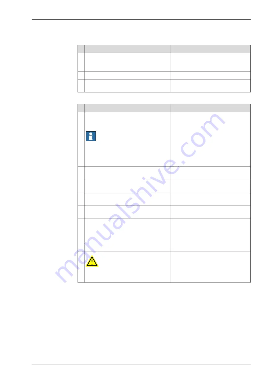
Refitting the axis 6 motor
Note
Action
Place the motor carefully in its mounting po-
sition with the wrist still placed on a work-
bench.
Note
Do not move the gears in the wrist when the
motor is removed! When refitting the motor
the gears in the wrist shall be in the same
position as they were before the removal.
1
In order to release the brakes connect the
24VDC power supply to the motor.
2
Tightening torque: 6 Nm
Secure the motor with its attachment screws.
3
M5x25
Refit the flexible coupling securing the axes
6 motor to the rod.
4
See
Replacing the wrist unit, IRB 1600ID
Refit the wrist.
5
Calibration is described in a separate
calibration manual enclosed with the cal-
ibration tools.
Recalibrate the robot.
6
General calibration information is included
in section
.
DANGER
Make sure all safety requirements are met
when performing the first test run.
7
Product manual - IRB 1520
253
3HAC043435-001 Revision: L
© Copyright 2012-2020 ABB. All rights reserved.
4 Repair
4.6.4 Replacing the axis 6 motor
Continued
Summary of Contents for IRB 1520
Page 1: ...ROBOTICS Product manual IRB 1520 ...
Page 8: ...This page is intentionally left blank ...
Page 16: ...This page is intentionally left blank ...
Page 74: ...This page is intentionally left blank ...
Page 132: ...This page is intentionally left blank ...
Page 288: ...This page is intentionally left blank ...
Page 300: ...This page is intentionally left blank ...
Page 302: ...This page is intentionally left blank ...
Page 308: ......
Page 309: ......


