2.3.4 Orienting and securing the robot
General
This section details how to orient and secure the robot at a horizontal level at the
installation site.
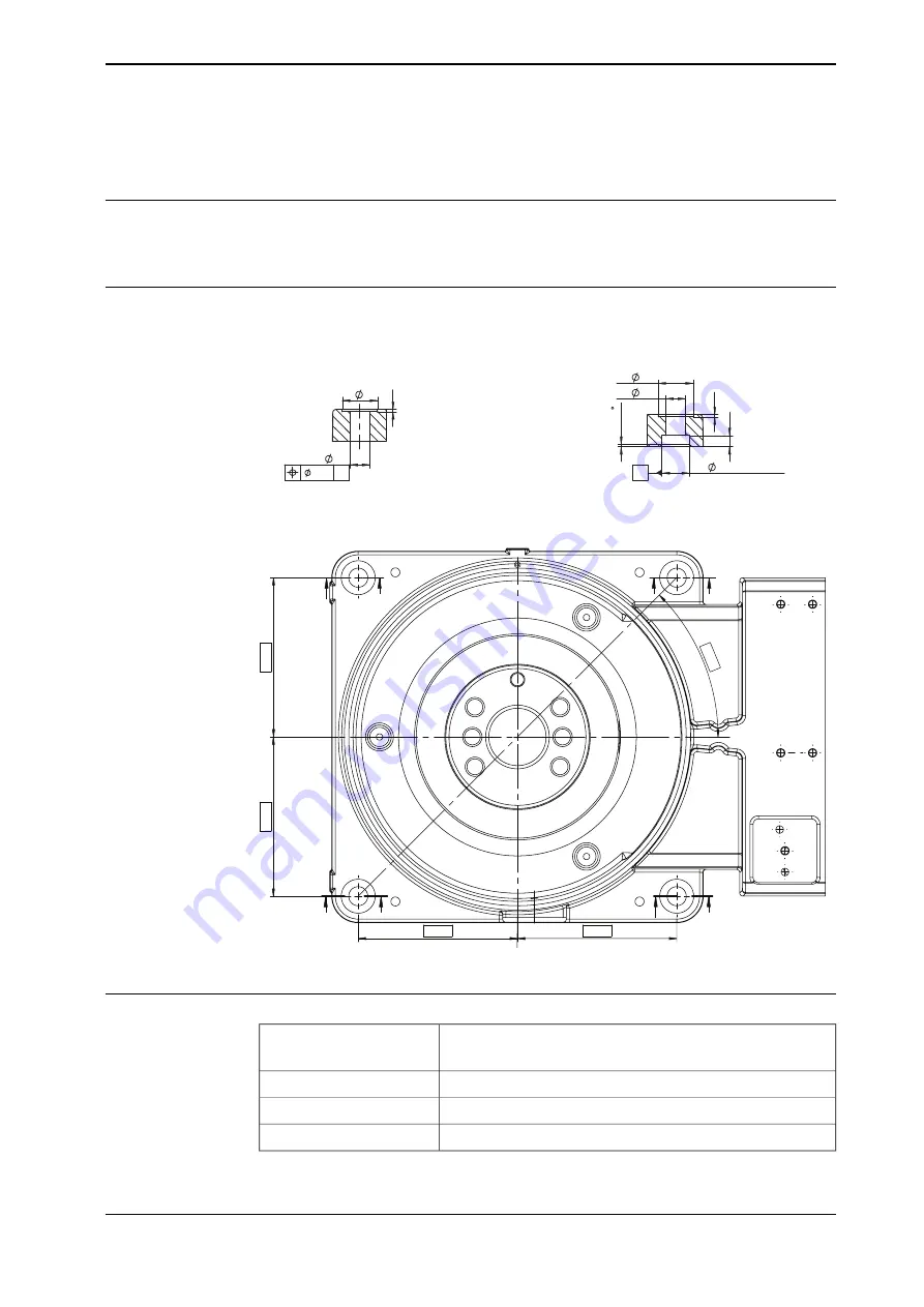
Hole configuration, base
The figure shows the hole pattern and dimensions of the robot base.
Two of the holes in the base (view G-G) are designed to include a guiding sleeve.
150
1
5
0
150
150
45°
F
F
G
G
F-F
G-G
G
G
F
F
0.5
A
2-
32
2
2-
18
A
2-
32
2
2
X
4
5
1
0
2-
25 H8
0
+0.033
2-
18
xx1100000293
Attachment bolts, specification
4 pcs
Attachment bolts
M16 x 45
30 x 17 x 3
Washers
8.8
Quality
200 Nm
Tightening torque
Continues on next page
Product manual - IRB 1520
55
3HAC043435-001 Revision: L
© Copyright 2012-2020 ABB. All rights reserved.
2 Installation and commissioning
2.3.4 Orienting and securing the robot
Summary of Contents for IRB 1520
Page 1: ...ROBOTICS Product manual IRB 1520 ...
Page 8: ...This page is intentionally left blank ...
Page 16: ...This page is intentionally left blank ...
Page 74: ...This page is intentionally left blank ...
Page 132: ...This page is intentionally left blank ...
Page 288: ...This page is intentionally left blank ...
Page 300: ...This page is intentionally left blank ...
Page 302: ...This page is intentionally left blank ...
Page 308: ......
Page 309: ......


