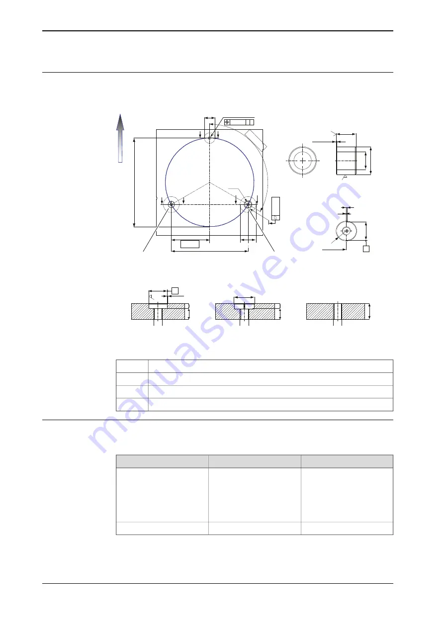
Dimension, mounting surface and guide bushing
The figure shows the dimension of the mounting surface and guide bushings.
G
G
Ø0.5 AB
Ø60
C
C
(3
X12
0º
)
B
B
D
0
.5
A
A
5
0
0
216.5
433 ±0.5
A-A
B-B
2x Ø 90
2x Ø 90
(37)
+0.024
-0.015
J8
Ø35
1x45º
1.6
C-C
(433±0.5)
B
R
+0
.0
2
4
-0
.0
1
5
J8
Ø
3
5
1
1.6
2.5
25
2x 1x45º
Ø
2
2
-0
.0
2
5
-0
.0
5
0
f7
Ø
3
5
(A)
A
(C
)
(D)
E
F
Ø
30 min
20 min
10
M16
20 min
10
M16
M16
xx1700001492
3x common zone
(C)
Position of the front of the robot
E
M16 (3 pcs)
F
Guide bushings (2 pcs)
G
Specification, attachment screws
The table specifies the type of securing screws and washers to be used to secure
the robot to the foundation or base plate.
Note
Dimension
Securing parts/Facts
6 pcs
M16 x 60 (installation directly
on foundation)
Securing screws, oiled
200 Nm
M16 x 70/80 (installation on
foundation or base plate, us-
ing guide bushings)
Quality 8.8
6 pcs
17 x 30 x 3
Washers
Continues on next page
62
Product manual - IRB 4600
3HAC033453-001 Revision: Y
© Copyright 2009-2021 ABB. All rights reserved.
2 Installation and commissioning
2.3.4 Orienting and securing the robot
Continued
Summary of Contents for IRB 4600
Page 1: ...ROBOTICS Product manual IRB 4600 ...
Page 8: ...This page is intentionally left blank ...
Page 334: ...This page is intentionally left blank ...
Page 368: ...This page is intentionally left blank ...
Page 376: ...This page is intentionally left blank ...
Page 390: ...This page is intentionally left blank ...
Page 392: ...This page is intentionally left blank ...
Page 398: ......
Page 399: ......


