2.4.9 Fitting equipment to the robot
General
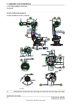
Extra loads can be fitted on the upper arm housing, the lower arm, and on the
frame. Definitions of distances and masses are shown in the following figures. The
robot is supplied with holes for fitting extra equipment (see figure in
). Maximum allowed arm load depends on center of
gravity of arm load and robot payload.
Note
All equipment and cables used on the robot, must be designed and fitted not to
damage the robot and/or its parts.
Frame (hip load)
Extra load can be fitted on the frame.
Description
J
H
= 100 kgm
2
Permitted extra load on frame
J
H
= J
H0
+ M4 x R
2
Recommended position (see the fol-
lowing figure)
where:
•
J
H0
is the moment of inertia of the equipment
•
R is the radius (m) from the center of axis 1
•
M4 is the total mass (kg) of the equipment
including bracket and harness (≤ 250 kg)
Continues on next page
Product manual - IRB 6790
81
3HAC063331-001 Revision: B
© Copyright 2019 - 2020 ABB. All rights reserved.
2 Installation and commissioning
2.4.9 Fitting equipment to the robot
Summary of Contents for IRB 6790
Page 1: ...ROBOTICS Product manual IRB 6790 ...
Page 8: ...This page is intentionally left blank ...
Page 16: ...This page is intentionally left blank ...
Page 38: ...This page is intentionally left blank ...
Page 164: ...This page is intentionally left blank ...
Page 612: ...This page is intentionally left blank ...
Page 638: ...This page is intentionally left blank ...
Page 644: ...This page is intentionally left blank ...
Page 658: ...This page is intentionally left blank ...
Page 660: ...This page is intentionally left blank ...
Page 667: ......


