Operating Instructions
Temperaturregler
Installation and electrical
connection
Operating Instructions | 1473-1-8290
— 9 —
Pos: 34 /#Neustr uktur#/Online-Dokumentati on (+KN X)/Montage/alle Geräte/M ontage - U P-Dosen - D IN 49073-1 oder geeignetes Aufputzgehaeuse - Ohne Docvari abl e @ 25\mod_1340354979636_15.docx @ 219890 @ @ 1
The flush-mounted insert must only be installed in flush-mounted wall boxes according to DIN 49073-1, Part 1, or
suitable surface-mounted housings.
Pos: 35 /#Neustr uktur#/Online-Dokumentati on (+KN X)/Montage/T emper aturregler/M ontag e 1094....1097 @ 26\mod_1342768559622_15.docx @ 224432 @ @ 1
The temperature controller is suitable for use in dry rooms only.
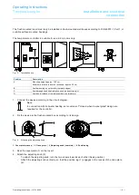
Fig. 3: Installation site
Position
Description
A
Mounting height: approx. 150 cm
Minimum distance to doors or windows: approx. 30 cm
B
Avoid mounting on cold walls (thermal bridges)
C
Avoid draught and heat radiation, such as direct sunlight
D
Avoid heat radiation from adjacent devices (dimmers)
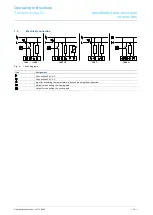
1. Connect the device according to the circuit diagram.
Note
In connection with hot-water heating, servo valves of "closed when de-energized“ design are
required for the controller.
2. Fix the device in the flush-mounted box according to its design.
Fig. 4: Attaching the adjusting knob
1 Cover plate (cover) | 2 Drive plate | 3 Adjusting knob (rear side) | 4 Position lug
3. Seat the cover plate (1) on the insert.
4. Attach the adjusting knob (3):
- To attach the adjusting knob, turn the two arrows towards each other (basic position).
- Attach the adjusting knob vertically, so that the position lug (1) engages in the recess of the drive plate
(2).
Pos: 36 /#Neustr uktur#/Online-Dokumentati on (+KN X)/Steuer modul e - Online-Dokumentation (--> Für alle Dokumente <--)/++++++++++++ Seitenu+++++++++++ @ 9\mod_1268898668093_0.docx @ 52149 @ @ 1

