Installation and commissioning guide
1ZSC000563-AAF EN, REV. 4, 2021-06-23
67
7.
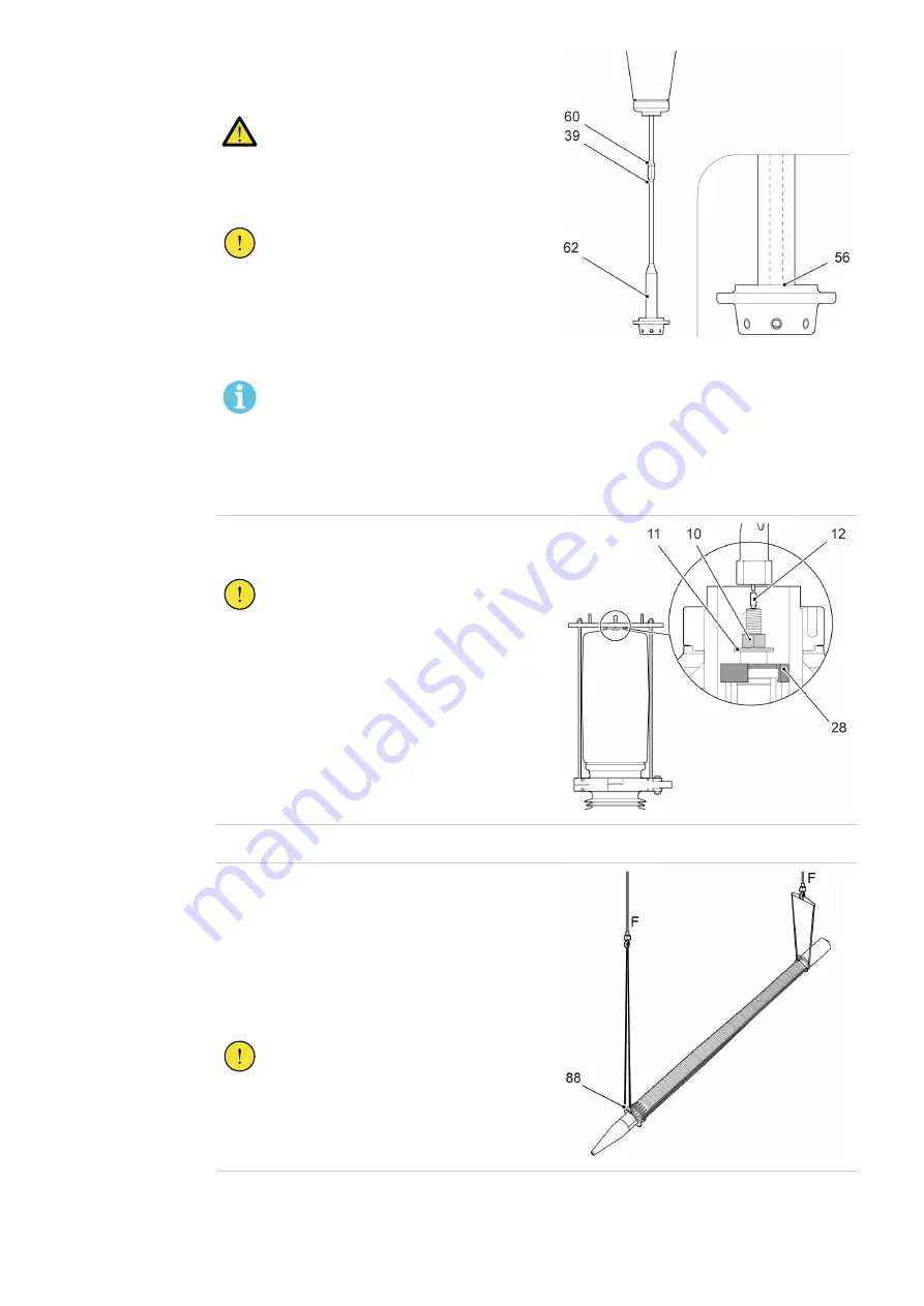
Disassemble the draw rod at the lower joint (39).
Use the key grip on the lower draw rod.
DANGER!
Make sure that the upper draw rod
does not fall down when the lower
joint (39) is disassembled.
CAUTION!
Do not disassemble the joint (60), this
increases the risk of incorrect
assembly.
The joint (60) is locked with
tread-locking fluid grade 42.
NOTE!
The bushing can have an optional joint,
or the bottom contact unlocked (56),
refer to the specifications for your
bushing.
The guiding cone (62) is loose.
G005033
8.
Pull up the draw rod, and install the washer (11)
and nut (10).
CAUTION!
Make sure that the centering ring (28)
is in position, it is necessary for the
correct installation of the draw rod.
G006965
9.
Remove the pull-through cord (12).
10.
Lift the bushing to a position above the floor and
turn the bushing to a horizontal position.
1.
Install the lifting tool (88) to the flange.
2.
Install soft lifting slings from the lifting tool
(88) to a second crane.
3.
Lower the upper part of the bushing. Stop
when the bushing is in a horizontal position.
CAUTION!
Do not let the bushing come in contact
with the floor while lowering the
bushing to a horizontal position.
Contact with the floor can cause
damage to the bushing.
G007209
Summary of Contents for 1ZSC902110-AAA
Page 12: ...12 Installation and commissioning guide 1ZSC000563 AAF EN REV 4 2021 06 23 ...
Page 18: ...18 Installation and commissioning guide 1ZSC000563 AAF EN REV 4 2021 06 23 ...
Page 78: ...78 Installation and commissioning guide 1ZSC000563 AAF EN REV 4 2021 06 23 ...
Page 82: ...82 Installation and commissioning guide 1ZSC000563 AAF EN REV 4 2021 06 23 ...


