- 5 -
2.2
PRESSURE AND TEMPERATURE LIMITS
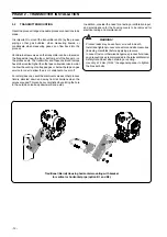
The maximum allowable pressure (PS) and maximum/minimum
allowable temperature (TS) of the pressure transmitter, for
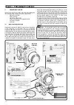
the European market are indicated on the tag plate (ref. D of
Figure 1), in the U.S. please refer to the instrument data sheets
available at: http://138.221.224.36 searching for "264 and
sheet" or from local ABB representatives.
PS and TS are defined according to the European Pressure
Equipment Directive 97/23/EC (PED). For Temperature, the
listing is for the min and max process temperature limits at
which the instrument can be exposed, for Pressure this listing
should be considered the maximum working pressure limit to
which the transmitter can be exposed without damage (to the
transmitter). These limits are valid when the transmitter is
installed according to the instructions in this manual.
WARNING !
For potentially explosive atmosphere applications see the
temperature range specified in the certificate/approval
relevant to the intended type of protection.
PS values
The transmitter can be exposed without leaking to line pressure
of up to:
Models 264DS, 264PS, 264VS, 264DF, 264PF, 264VF
- 2MPa, 20bar, 290psi for sensor code A
- 7MPa, 70bar, 1015psi for sensor code B
- 16MPa, 160bar, 2320psi for sensor code E
- 21MPa, 210bar, 3045psi for sensor codes F to S
- 1MPa, 10bar, 145psi for Kynar-PVDF
- 16MPa, 160bar, 2320psi for AISI 316 ss NACE bolting
Model 264BS
- 41MPa, 410bar, 5945psi
Model 264DH
- 230psi for ASME CL150 flange
- 600psi for ASME CL300 flange
The pressure limit decreases with increasing temperature
above 100
°
F (38
°
C), according to ASME B16.5 standards.
- 13.5bar for EN PN16 flange
- 33.8bar for EN PN40 flange
The pressure limit decreases with increasing temperature
above 50
°
C according to EN 1092-1 standards.
Proof pressure
The transmitter can be exposed without leaking to line pressure
of up to:
Models 264DS, 264PS, 264VS, 264DF, 264PF, 264VF
- 48MPa, 480bar, 6960psi
Model 264BS
- 61.5MPa, 615bar, 8917psi
Model 264DH
- up to two times the flange rating.
Meet ANSI/ISA–S 82.03 hydrostatic test requirements and
SAMA PMC 27.1.
Other 264Dx models using direct mount and/or remote
seal(s) are compliant to SEP (Sound Engineering Practice).
PHASE 1 - PRELIMINARY CHECKS
WARNING !
In order to assure the proper containment of the process
fluid by the transmitter, it is recommended that any part,
related to process fluid containment, be supplied only by
ABB or authorized agents.
The spare parts list is available at: http://138.221.224.36
searching for “SL/26*” or from local ABB representatives.
The storage conditions must be within the following limits,
Lower limit: –50
°
C (–58
°
F); –40
°
C (–40
°
F) for LCD indicators
Upper limit: +85
°
C (+185
°
F) otherwise some material such as
gaskets may be damaged and cannot assure proper fluid
containment.
2.3
OPERATING VOLTAGE LIMITS
The transmitter is designed to provide a current transmission
signal of 4 to 20 mA dc on the same wires that are carrying the
power supply (two-wire transmitter).
The transmitter operates on a minimum voltage of 10.5 Vdc to
a maximum of 42 Vdc and is protected against polarity inversion.
The transmitter operates from 10.5 to 42 Vdc with no load.
The operating voltages range for fieldbus versions, both polarity
independent, are as follows:
- PROFIBUS PA from 9 to 32 Vdc (17.5 Vdc for EEx ia)
- FOUNDATION Fieldbus from 9 to 32 Vdc (for EEx ia
applications 24 Vdc max with entity or 17.5 Vdc max with
FISCO)
Some communication problems may occur, in cases the loop
resistance is increased by long wires or additional devices like
meters, safety barriers, surge protection, remote indicators,
etc.
If this is the case, please refer to the reference manual for
further details (the manual is available at www.abb.com inserting
in the “search” tool the keyword “IM/26X”) or from local ABB
representatives.
For EEx ia and intrinsically safe (FM, CSA and SAA) approvals,
the power supply must not exceed 30 Vdc. In some countries
the maximum power supply voltage is limited to a lower value.
The transmitter insulation resistance (terminals to earth) is
>100M
Ω
at 1000VDC.
CAUTION
Do not arc-weld any pipe-connected to
the transmitter as this could break the electrical insulation
and damage the electronic part of the transmitter.


