Electrical
connection
IM/265D/V-EN-02 265Dx,
265VS
33
Pos: 13.16 /Überschriften/1.1/1-spaltig/S - U/Schutzleiteranschluss / Erdung @ 1\mod_1147681845359_3101.doc @ 11059
5.5
Protective conductor/Grounding
Pos: 13.17 /Erdung/Druck/Druckmessumformer/Allgemein/Schutzleiteranschluss / Erdung @ 2\mod_1149835604343_3101.doc @ 28855
The transmitter operates within the specified levels of accuracy for common-mode voltages of
up to 250 V between signal lines and housings.
As a general rule, the transmitter must be supplied by a voltage source with a maximum output
voltage of 60 VDC, which is safely isolated from the line supply. To ensure that the safety
objectives of the Low Voltage Directive are achieved, and the corresponding EN 61010
regulations governing installation of electrical equipment are observed, the housing must have a
protective system (e.g., grounding, protective conductor) that is activated if voltages > 60 VDC
occur.
Pos: 13.18 /Überschriften/1.1/1-spaltig/G - I/Integrierter Blitzschutz (optional) @ 2\mod_1149835881031_3101.doc @ 28877
5.6
Integrated lightning protection (optional)
Pos: 13.19 /Elektrischer Anschluss/Druck/Druckmessumformer/Allgemein/Integrierter Blitzschutz @ 2\mod_1149836160250_3101.doc @ 28897
The transmitter housing must be connected using the grounding terminal (PA), by means of a
short connection with the equipotential bonding. Equipotential bonding (minimum diameter:
4 mm
2
(AWG 12) is required throughout the cable routing area.
In the case of transmitters with integrated lightning protection (optional), the intrinsically safe
circuit is connected to the equipotential bonding for safety reasons.
Important
Test voltage withstand capability can no longer be ensured when this protective circuit is used.
Pos: 13.20 /Überschriften/1.1/1-spaltig/A - C/Aufbau des Kommunikationskreises @ 1\mod_1147683286828_3101.doc @ 11075
5.7
Communication setup
Pos: 13.21 /Elektrischer Anschluss/Druck/Druckmessumformer/Allgemein/Aufbau des Kommunikationskreises @ 2\mod_1149836641921_3101.doc @ 28928
(4 … 20 mA; HART protocol)
The transmitter can be operated via a modem, using a PC or laptop. The modem can be
connected to the transmitter in parallel at any point in the signal circuit. Communication between
the transmitter and modem occurs via AC signals that are superimposed on the analog
4 ... 20 mA output signal. This modulation occurs without averaging and does not, therefore,
affect the measuring signal.
Communication between the transmitter and PC or laptop is only possible if the signal circuit is
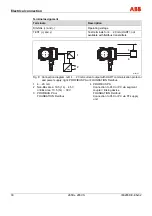
set up as shown in Fig. 12. The resistance between the connection point for the FSK modem
and the supply unit must be at least 250
Ω
(including internal resistance of the supply unit). If
this value is not achieved within the context of normal installation, an additional resistor must be
used.
In the case of supply modules with HART communication, the additional resistor is often
installed permanently by the manufacturer. Some of these modules offer the option of
communicating directly over the supply module in the operating mode "FSK bus".
Power can be supplied by supply units, batteries, or power supplies; these must be designed to
ensure that the operating voltage U
B
of the transmitter always remains between 10.5 VDC and
45 VDC (for LCD displays with backlighting: 14 … 45 VDC
)
.
In addition, the maximum current of 20 … 22.5 mA resulting from overranging must be
considered, depending on the corresponding parameterization. This yields the minimum value
for U
S
. If additional signal receivers (e.g., displays) are looped into the signal circuit, their
resistance must also be considered.
Summary of Contents for 265DS
Page 87: ......

