Electrical
connection
IM/265D/V-EN-02 265Dx,
265VS
35
Pos: 13.23 /Überschriften/1.1/1-spaltig/A - C/Anschlusskabel @ 1\mod_1147683526078_3101.doc @ 11091
5.8
Connecting cable
Pos: 13.24 /Elektrischer Anschluss/Druck/Druckmessumformer/Allgemein/Anschlusskabel @ 3\mod_1157616660609_3101.doc @ 39583
Communication between the transmitter and PC or laptop is only possible if the cabling meets
the following requirements:
It is recommended that shielded, twisted pair cables are used.
The minimum wire diameter depends on the line length.
Line lengths up to 1,500 m (4,921 ft)
: 0.51 mm (0.02 inch)
Line lengths above 1,500 m (4,921 ft)
: 0.81 mm (0.03 inch)
The maximum line length is limited.
Dual-core cable
: 3,000 m (9,842 ft)
Multi-core cable
: 1,500 m (4,921 ft)
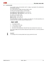
The actual possible line length of the electrical circuit depends on the total capacitance and
resistance, and can be estimated using the following formula:
C
10000
f
C
C
R
6
10
65
L
+
−
×
×
=
L
= Line length in meters
R
= Total resistance in
Ω
(ohms)
C
= Line capacitance in pF/m
C
f
= Maximum internal capacitance of the HART field devices located in the circuit, in pF
Avoid routing cables with other electrical cables (with inductive load, etc.) or near large electrical
equipment.
Pos: 13.25 /Erdung/Druck/Druckmessumformer/Allgemein/Hinweis zur Erdung der Abschirmung @ 2\mod_1149837270140_3101.doc @ 28949
Important
The shielding for the connecting cable should only be grounded at one side.
Pos: 13.26 /======= Seitenumbruch ======== @ 0\mod_1126532365768_3101.doc @ 3830
Summary of Contents for 265DS
Page 87: ......

