background image

22   OI/266/HART-EN Rev. D 

| 2600T Series Pressure transmitters

266 Models - HART

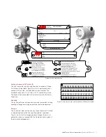
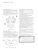
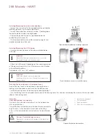
Transmitter housing rotation

To improve field access to the wiring or the visibility of the 
optional LCD meter, the transmitter housing may be rotated 
through 360° and fixed in any position. A stop prevents the 
housing from being turned too far.
In order to proceed with housing rotation, the housing stop 
tang-screw has to be unscrewed by approximately 1 rotation 
(do not pull it out) and, once the desired position has been 
reached, retightened.

Integral Display Rotation

In case an optional integral display meter is installed, it is 
possible to mount the display in four different positions rotated 
clockwise or counterclockwise with 90° steps.
To rotate the LCD, simply open the windowed cover 
(Hazardous area prescriptions must be respected), pull-out the 
display housing from the communication board.. Reposition 
the LCD connector according to the new desired position. 
Push back the LCD module on the communication board. Be 
sure that the 4 plastic fixing locks are properly in place.

Impulse piping connection for standard instruments

In order for the pipes to be laid correctly, the following points 
must be observed:
– The measuring pipes must be as short as possible and free 
from sharp bends.
– Lay the impulse piping in such a way that no deposits can 
accumulate in them. Gradients should not be less than approx. 
8 % (ascending or descending).
– The measuring pipes should be blown through with 
compressed air or, better yet, flushed through with the 
measuring medium before connection.
– Where a fluid/vaporous measuring medium is being used, the 
liquid in both measuring pipes must be at the same level. If a 
separating liquid is being used, both measuring pipes must be 
filled to the same level (266Dx and 266Mx).
– Although it is not absolutely necessary to use balancing 
vessels with vaporous measuring media, measures must be 
taken to prevent steam entering the measuring chambers of 
the measuring equipment (266Dx and 266Mx).
– It may be necessary to use condensate vessels, etc., with 
small spans and vaporous measuring media (266Dx and 266Mx).
– If using condensate vessels (steam measurement), you 
should ensure that the vessels are at the same elevation in the 
differential pressure piping (266Dx and 266Mx).
– As far as possible, keep both impulse lines at the same 
temperature (266Dx and 266Mx).
– Completely depressurize the impulse lines if the medium is a 
fluid.
– Lay the impulse lines in such a way that gas bubbles (when 
measuring fluids) or condensate (when measuring gases) can 
flow back into the process line.
– Ensure that the impulse lines are connected correctly (High 
and Low pressure sides connected to measuring equipment, 
seals, etc.).
– Make sure the connection is tight.
– Lay the impulse line in such a way that prevents the medium 
from being blown out over the measuring equipment.


Caution 

Process leaks may cause harm or result in death.
Install and tighten process connectors and all accessories (including 
manifolds) before applying pressure. In case of toxic or otherwise 
dangerous process fluid, take any precautions as recommended in 
the relevant Material Safety Data Sheet when draining or venting. 
Use only a 12 mm (15/32 “) hexagonal spanner to tighten the 
bracket bolts.

Figure 22: Housing rotation

Figure 23: LCD rotation

Summary of Contents for 266 HART Series

Page 1: ...2600T Series Pressure Transmitters 266 Models HART Operating Instruction OI 266 HART EN Rev D 2600T Series Pressure Transmitters Engineered solutions for all applications ...

Page 2: ...using rotation 22 Integral display rotation 22 Impulse piping connection for standard instruments 22 Process connection considerations 23 Kynar inserts connection 23 Installation recommandations 24 Transmitter wiring 28 Cable connection 28 Analogue output HART transmitter wiring 29 Supply requirement 29 Wiring procedure 30 Electrical connection via connectors 30 Grounding 31 Protective grounding 3...

Page 3: ...h America 70 Additional instruction for IEC 61508 certified device 71 Safety philosophy 71 Application 71 Physical environment 71 Role and responsibilities 71 Management of functional safety 71 Information requirements 71 Overall safety life cycle information 71 Applicable laws and standards 71 System safety requirement assignment 72 System structure 72 Safety requirement allocation 72 Safety rout...

Page 4: ...owing center of excellence for ABB Pressure products ABB S p A Via Statale 113 22016 Lenno Co Italy Tel 39 0344 58111 Fax 39 0344 56278 ABB Automation Product GmbH Schillerstrasse 72 D 32425 Minden Germany Tel 49 551 905534 Fax 49 551 905555 ABB Inc 125 E County Line Road Warminster PA 18974 USA Tel 1 215 6746000 Fax 1 215 6747183 ABB Inc 3450 Harvester Road Burlington Ontario L7N 3W5 Canada Tel 1...

Page 5: ...ull compliance with the general safety requirements must be observed during operation of the device In addition to the general information the individual sections in the manual contain descriptions of processes or procedural instructions with specific safety information Only by observing all of the safety information can you reduce to the minimum the risk of hazards for personnel and or environmen...

Page 6: ...g protection type must be observed Warranty prevision Using the device in a manner that does not fall within the scope of its intended use disregarding this manual using under qualified personnel or making unauthorized alterations releases the manufacturer from any liability for any resulting damage This makes the manufacturer s warranty null and void Plates and symbols Danger Serious damage to he...

Page 7: ...ng storage transport use and disposal This includes the environmentally friendly use of natural resources ABB conducts an open dialog with the public through its publications This product solution is manufactured from materials that can be reused by specialist recycling companies Information on WEEE Directive 2002 96 EC Waste Electrical and Electronic Equipment This product or solution is not subj...

Page 8: ...the scope of operator responsibility check the following as part of a regular inspection Pressure bearing walls lining of the pressure device Measurement related function Leak tightness Wear corrosion Warning Risk to persons There is no EMC protection or protection against accidental contact when the housing cover is open There are electric circuits within the housing which are dangerous if touche...

Page 9: ...tant These two pictures show only two different kinds of transmitters equipped with Barrel type housing Please consider that DIN housings are available Figure 1 Differential pressure transmitter components Figure 2 Gauge absolute pressure transmitter components 1 TTG display L5 option 2 LCD display L1 option 1 2 1 2 ...

Page 10: ...ent depending on the selected options Football adapter to NPT f and gaskets Bracket kit Flushing rings Identification The instrument is identified by the data plates shown in Figure 3 The certification plate ref A contains the certification related parameters for use in Hazardous area The Nameplate ref B provides information concerning the model code maximum working pressure range and span limits ...

Page 11: ...ODUCTCODE SEAL H SEAL L SPEC REQUEST LRL URL SPAN LIMITS POWER SUPPLY OUTPUTSIGNAL ABB S p A Made in Italy TS PS SERIAL NUMBER SENSOR DIAPH FILL FLANGE CONN GASKET S H DIAPH FILL LDIAPH FILL SEAL HW Rev MD PED MWP OVP IS Sec Intrinseque Entity CLI ZONE0AEx ExiaIICT6 T5 T4 CLI DIV1 GPABCDIS CLII DIV1 GPEFG CLIIIDIV1when conn perdwgDH3173ENCL4X FISCOFieldInstrument DUALSEAL II1GExiaIICT6 II1 2GExiaI...

Page 12: ...type IP66 IP67 according tonIEC 60529 or NEMA 4X according to NEMA 250 The first number indicates the type of protection the integrated electronics have against the entry of foreign bodies including dust 6 means that the housing is dust proof i e no ingress of dust The second number indicates the type of protection the integrated electronics have against the entry of water 6 means that the housing...

Page 13: ...icle 3 paragraph 3 They have not been subject to a conformity validation These instruments were designed and manufactured acc to SEP Sound Engineering Practices Mounting a Differential Pressure sensor transmitter 266DS 266MS 266PS 266DR 266PR 266MR The pressure transmitter models 266DS 266MS and 266PS can be mounted directly on the manifold A mounting bracket for wall or pipe mounting 2 pipe is al...

Page 14: ...re of the drain vent valves position so that when the process fluid is removed during the drain vent operation it is directed down and away from technicians It is recommended to mount the transmitter to prevent this possible source of damage for unskilled operators Figure 6 Drain vent valves configuration respectively V1 V2 V3 Bracket mounting optional Different mounting brackets are available ple...

Page 15: ...2 28 55 2 17 Figure 8 Differential Pressure Style transmitter with barrel housing installed on a vertical pipe with optional bracket B2 96 8 3 81 100 3 94 for NACE bolting 179 7 02 91 3 58 145 5 70 54 2 13 78 3 07 with d v valve 29 1 14 18 0 71 18 0 71 210 8 28 58 2 28 55 2 17 66 2 60 with plug 41 3 1 63 65 2 53 102 4 02 29 1 12 9 0 35 Figure 7b Differential Pressure Style transmitter High Static ...

Page 16: ...re Style transmitter with DIN housing installed on a Vertical pipe with optional bracket B2 installation for LIQUID measurements 129 5 06 197 7 73 72 2 83 116 4 57 136 5 35 178 6 99 183 7 19 29 1 14 18 0 71 55 2 17 113 4 45 87 3 42 18 0 71 Figure 9 Differential Pressure Style transmitter with DIN housing installed on a Vertical pipe with optional bracket B2 installation for AIR GAS measurements ...

Page 17: ...e 11 Differential Pressure Style transmitter with barrel housing and Kynar inserts installed on a horizontal pipe with optional bracket B2 54 2 13 123 4 86 113 4 43 179 7 02 91 3 58 29 1 14 18 0 71 18 0 71 55 2 17 58 2 28 210 8 28 113 4 45 72 2 83 Figure 12 Differential Pressure Style transmitter with barrel housing and Kynar inserts installed on a vertical pipe with optional bracket B2 ...

Page 18: ...led on a box pipe with optional bracket for SST housing B5 B2 Pipe and wall mounting bracket details All the bolts and nuts supplied are necessary for the installation on pipe In case a panel or wall installation will be done the U bolt and the U bolt nuts and washers will not have to be used The bolts for panel mounting are not within the scope of supply Figure 13 Pipe and wall mounting bracket k...

Page 19: ...ent the zero point can be corrected via the zero push button or via the set PV to zero command Please refer to the configuration section for further details For transmitters without diaphragm seals the Vent Drain considerations below should be taken into consideration Figure 16 Model 266H or 266N Hi overload resistant P Style transmitter with barrel housing installed on a 2 pipe with optional brac...

Page 20: ...re 17 Model 266G or 266A P Style transmitter with barrel housing installed on a 2 pipe with optional bracket B1 carbon steel or B2 Stainless Steel 316L B1 and B2 Barrel housing bracket details 1 U bolt 2 U bolt fixing bolt and washer 3 Transmitter fixing bolts 4 B1 or B2 bracket 1 3 4 2 Figure 18 Pipe and wall mounting bracket kit B1 and B2 for P style transmitter with Barrel housing ...

Page 21: ... a 2 pipe with optional bracket B2 Stainless Steel 316L 56 2 20 max 105 4 13 128 5 04 83 3 27 72 2 83 18 0 71 145 5 71 1 2 14 NPT 117 4 60 72 2 83 66 2 60 120 4 72 29 1 14 18 0 71 30 1 19 11 0 43 22 0 87 width across flats of exagon Figure 20 Model 266G or 266A P Style transmitter with DIN housing installed on a 2 pipe with optional bracket B2 Stainless Steel 316L Figure 21 Pipe and wall mounting ...

Page 22: ...fore connection Where a fluid vaporous measuring medium is being used the liquid in both measuring pipes must be at the same level If a separating liquid is being used both measuring pipes must be filled to the same level 266Dx and 266Mx Although it is not absolutely necessary to use balancing vessels with vaporous measuring media measures must be taken to prevent steam entering the measuring cham...

Page 23: ...s or 15Nm for Stainless steel NACE bolts Deviations for models 266Mx 266Rx and for PTFE O rings pretightening hand tight Pretightening to 10 Nm Final tightening to 50 Nm For model 266PS 266VS and 266RS it is only possible to have one adapter with low pressure side flange without process connection and drain vent valve For high static model 266DSH x H tighten the bolts to a torque value of 40 Nm re...

Page 24: ... gate valves Slowly open high pressure A valve to admit process fluid to both sides of primary Vent or drain the primary unit and then close the valves Open the B valve and close the equalizing valve Gas or liquid with solids in suspension Flow Measurement Place the taps to the top or side of the line Mount the transmitter above the taps The process fluid must enter the transmitter primary Open eq...

Page 25: ...aximum level of the tank Liquid Level measurement with closed tanks and condensable fluids wet leg Mount the transmitter at the same height or below the lowest level to be measured Connect the H side of the transmitter to the bottom of the tank Connect the L side of the transmitter to the upper part of the tank Fill the vertical section of the connecting line to the upper part of the tank with a c...

Page 26: ...de of the transmitter to the atmosphere in this case a gauge pressure is shown the L side is already vented to the atmosphere Pressure or Absolute Pressure measurement of a tank Place the taps in the upper part of the tank Mount the transmitter above the elevation of the process tap Connect the transmitter to the tank Figure 30 Level measurement on open tank with P style transmitter Figure 31 Gaug...

Page 27: ...densable vapor in a pipe Place the tap at the side of the line Mount the transmitter below the tap Connect the H side of the transmitter to the pipe Fill the vertical section of the connecting line to the tap with a compatible liquid through the dedicated filling tee Figure 32 Gauge or absolute pressure measurement of a liquid in a pipe with DP and P style transmitter Figure 33 Gauge or absolute p...

Page 28: ...U PROFIBUS PA and FOUNDATION Fieldbus M12 x 1 or 7 8 plug The screw terminals are suitable for wire cross sections of up to 2 5 mm2 AWG 14 Warning General risks Observe the applicable regulations governing electrical installation Connections must only be established in a dead voltage state Since the transmitter has no switch off elements overvoltage protection devices lightning protection and volt...

Page 29: ...L 4 M N O 5 P Q R 6 S T U 7 V W X 8 Y Z 9 0 PV REVIE W SERIAL LINK TRI M F1 F2 F3 F4 CONF 2 1 1 2 5 4 3 6 HART hand held communicator may be connected at any wiring termination point in the loop providing the minimum resistance is 250 ohm If this is less than 250 ohm additional resistance should be added to allow communications The handheld terminal is connected between the resistor and transmitte...

Page 30: ...the terminal and the negative lead to the terminal Plug and seal the electrical ports Make sure that when the installation has been completed the electrical ports are properly sealed against entry of rain and or corrosive vapors and gases If applicable install wiring with a drip loop Arrange the drip loop so the bottom is lower than the conduit connections and the transmitter housing Put back the ...

Page 31: ... both the outside of the housing and in the plug for grounding PE the transmitter Both terminals are electrically connected to one another Protective Grounding All transmitters are supplied with an external ground connection for protective grounding Wire this ground connection to a suitable earth ground For a transmitter measuring loop an earth ground should maintain a resistance of 5 ohms or less...

Page 32: ... is connected to the output circuit or a modem is connected in parallel while there is a risk of explosion the sums of the capacitances and inductances of all circuits including the transmitter see EC type examination certificate must be equal to or less than the permissible capacitances and inductances of the intrinsically safe signal circuit see EC type examination certificate for the supply uni...

Page 33: ...ge value Apply the lower range value pressure 4 mA from the process or from a pressure transducer The pressure must be stable and applied with a high level of accuracy 0 05 observing the set damping value Press the Z button on the pressure transmitter for few seconds The output signal will be is set to 4 mA The span will remain unchanged Important A lower range value set using this method will be ...

Page 34: ...hand tight If necessary refer to the section Securing the housing cover in flameproof areas Figure 40 External pushbutton assembly components Figure 41 Windowed front cover and LCD display Securing the housing cover in flameproof areas Each of the front faces of the electronics housing features a locking screw hex head socket screw on the bottom side Install the housing cover to the housing by han...

Page 35: ... applies The first pressure value e g 0 mbar is always assigned to the 4 mA signal or 0 while the second pressure value e g 400 mbar is always assigned to the 20 mA signal or 100 To change the transmitter ranging apply the pressure for the lower range value and upper range value to the measuring equipment Make sure that the measuring limits are not exceeded Important Reducing station with adjustab...

Page 36: ...isplay and the transmitter In addition diagnostic information is provided To access the functionality of the HMI an activation procedure needs to be carried out The keypad activation procedure is different between the TTG Trough The Glass version and the conventional HMI The keys 1 4 2 and 3 are available for the menu con trolled configuration The menu submenu name is displayed above in the LCD di...

Page 37: ...be selected by acting on the keys 2 and 3 once on the display the desired sub menu icon will be visualized confirm your selection with the SELECT key 4 Follow the instruction on the screen to perform the configuration of the different parameters This menu allows the verification and the parameterization of the basic configuration of the 266 pressure transmitter The menu driven structure will guide...

Page 38: ...alization mode normal batch forward reverse forward reverse and forward reverse the configuration unit and conversion factor of totalizer 1 and 2 Furthermore it is possible to set up the values of the batch totalizer count direction present value and reload User will be able to add change delete the password as well as to reset all totalizers This menu allows you to monitor diagnostics messages re...

Page 39: ...to the next menu item Press the 4 key and set LRV value After entering the settings press the 1 key to move to the next menu item Press the 4 key and select the transfer function from the list with 2 3 After entering the settings press the ok 1 key to move to the next menu item Press the 4 key and set the damping After entering the settings press the 1 key to move to the next menu item This functi...

Page 40: ...40 OI 266 HART EN Rev D 2600T Series Pressure transmitters 266 Models HART Device Set up ...

Page 41: ...2600T Series Pressure transmitters OI 266 HART EN Rev D 41 ...

Page 42: ...42 OI 266 HART EN Rev D 2600T Series Pressure transmitters 266 Models HART ...

Page 43: ...2600T Series Pressure transmitters OI 266 HART EN Rev D 43 ...

Page 44: ...44 OI 266 HART EN Rev D 2600T Series Pressure transmitters 266 Models HART Display ...

Page 45: ...2600T Series Pressure transmitters OI 266 HART EN Rev D 45 ...

Page 46: ...46 OI 266 HART EN Rev D 2600T Series Pressure transmitters 266 Models HART ...

Page 47: ...hich is configurable in case the PV will be above the URV upper range value the signal will be driven to the High Saturation limit which is configurable too In case the transmitter diagnostic detects a failure the signal will be driven upscale or downscale according to the user preferences the failure direction is selected via the dip switch 4 and 5 on the communication board The exact value to wh...

Page 48: ...48 OI 266 HART EN Rev D 2600T Series Pressure transmitters 266 Models HART Calibrate ...

Page 49: ...2600T Series Pressure transmitters OI 266 HART EN Rev D 49 Totalizer ...

Page 50: ...50 OI 266 HART EN Rev D 2600T Series Pressure transmitters 266 Models HART ...

Page 51: ...2600T Series Pressure transmitters OI 266 HART EN Rev D 51 ...

Page 52: ...52 OI 266 HART EN Rev D 2600T Series Pressure transmitters 266 Models HART Diagnostics ...

Page 53: ...2600T Series Pressure transmitters OI 266 HART EN Rev D 53 Device Info ...

Page 54: ...54 OI 266 HART EN Rev D 2600T Series Pressure transmitters 266 Models HART Communication ...

Page 55: ...be activated using a Configuration Tool Digital LCD Integral Display Hand Held Communicator or PC based software as Asset Vision Basic The transfer function can be applied to the analog signal 4 to 20 mA only or also to the indication in engineering units vant operating instruction Square root Using the Square Root function the output in of the span is proportional to the square root of the input ...

Page 56: ...unction can be used for open channel flow measurement using ISO 1438 Vnotch triangular weirs see figure on the right where the relationship between the flow and the developed head h the differential pressure measured by the transmitter is proportional to h5 2 or square root of h5 Using this function the output in of the span is proportional to the square root of the fifth power of the input signal...

Page 57: ...LRV 2500mmH2O 20mA URV 2500mmH2O Transfer function Bidirectional flow Once configured as above the transmitter will deliver flowrate 100 l h reverse output 4 mA no flowrate output 12 mA Flow rate 100 l h output 20 mA Cylindric lying tank This function is used to measure the volumetric level into a cylindrical horizontal tank with flat ends The transmitter calculates the volume from the measured fi...

Page 58: ... If no communication resistor is present min 250 Ω you will need to install one in the line The handheld terminal is connected between the resistor and transmitter not between the resistor and supply unit A Transmitter B Supply unit communication resistor not provided in supply unit Figure 48 Communication setup with handheld terminal A Transmitter B Supply unit communication resistor not provided...

Page 59: ...usibility check You can call up context sensitive help at any time by pressing the F1 key Immediately after you have received the transmitter or before you change the configuration we recommend that you save the existing configuration data to a separate data storage medium via the path File_Save Configuration with the graphical user interface DTM System requirements Operating control program e g A...

Page 60: ...og Signal to Alarm F106 035 Unreliable Output Current The Device is not properly configured Check the device configuration Analog Signal to Alarm Sensor related error messages Error message Tx LCD message Possible cause Suggested action Tx response F120 016 Sensor Invalid The sensor signal is not being updated correctly as a result of an electronics failure sensor error or a poorly connected senso...

Page 61: ...the Sensor have been changed and a replacement operation for a new sensor has to be executed The replacement operation must be executed Only the data of the electronics can be copied into the sensor Move the SW 1 to Enable replace mode 1 Select with the SW 2 to New Sensor 1 Power Cycle the device Move the SW 1 to Disable replace mode 0 no effect M020 042 Replace Info The Electronics or the Sensor ...

Page 62: ...e device components and may require calibration replacement The compatibility of pressure trans mitter model and process conditions has to be checked A different installation type could be required e g use of remote seals no effect S052 031 Max Working Pres sure Exceeded The static pressure of the process exceeds the max working Pressure supported by the transmitter Exceeding the Max Working Press...

Page 63: ...mitter to the extent necessary for cleaning inspection repairs and replacement of damaged components Returns and removal Defective transmitters sent to the repairs department must wherever possible be accompanied by your own description of the fault and its underlying cause Warning General risks Before removing or disassembling the device check for hazardous process conditions such as pressure on ...

Page 64: ...a torque wrench to tighten the process flange nuts to a torque of 40 Nm let the flange stabilize for an hour unscrew the nuts and tighten again to 25 Nm Stainless Steel NACE Use a torque wrench to tighten the process flange nuts to a torque of 25 Nm let the flange stabilize for an hour and perform the final tightening to 25 Nm 266DSH x H High static option Viton Gaskets All bolting Use a torque wr...

Page 65: ...ng c Continue to rotate the electronic housing counterclockwise until its complete removal as shown by the figure here on the right Unscrew the fixing bolts from the transducer and remove the process flanges The orings placed between the diaphragm and the flange Viton or PTFE must be replaced after every disassembly Reassemble the flanges following the steps above in reverse order The 266 can reco...

Page 66: ...ous media D Dust dangerous media T85 C Maximum surface temperature of the transmitter enclosure with a Ta ambient temperature 40 C for Dust not Gas with a dust layer up to 50 mm depth Important The number close to the CE marking of the transmitter safety label identifies the Notified Body which has responsibility for the surveillance of the production The other marking refers to the protection typ...

Page 67: ...tection level a IIC Gas group T4 Temperature class of the transmitter which corresponds to 135 C max with a Ta from 50 C to 85 C T5 Temperature class of the transmitter which corresponds to 100 C max with a Ta from 50 C to 40 C T6 Temperature class of the transmitter which corresponds to 85 C max with a Ta from 50 C to 40 C About the applications this transmitter can be used in Zone 0 Gas classifi...

Page 68: ...re can be used in Zone 1 Gas only see sketch below Reason of this is the process part of the transmitter normally called primary transducer that provides inside separation elements to seal off the electrical sensor from the continuously hazardous process according to the EN 60079 26 and EN 60079 1 About Dust application the transmitter is suitable for Zone 21 according to the EN 61241 1 as it is s...

Page 69: ...ponds to 135 C max with a Ta from 50 C to 85 C T5 Temperature class of the transmitter which corresponds to 100 C max with a Ta from 50 C to 40 C T6 Temperature class of the transmitter which corresponds to 85 C max with a Ta from 50 C to 40 C About the applications this transmitter can be used in Zone 2 Gas and Zone 22 Dust classified areas unlikely infrequent hazard as it is shown on the followi...

Page 70: ...5 Explosionproof Electrical Equipment FM 3810 Electrical and Electronic Test Measuring and Process Control Equipment NEMA 250 Enclosure for Electrical Equipment 1000 Volts Maximum The 2600T Series pressure transmitters have been certified by FM Approvals for the following Class Divisions and Gas groups hazardous classified locations temperature class and types of protection Explosionproof US for C...

Page 71: ...fied as responsible for management of functional safety activities shall be informed of the responsibilities assigned to them All persons involved in any overall E E PES or software safety lifecycle activity including management activities should have the appropriate training technical knowledge experience and qualifications relevant to the specific duties they have to perform Management of functi...

Page 72: ...in the Safety Instrumented System Commissioning Overall system functionality The activity to validate the required safety functionality of the system together with the pressure transmitter according to the Safety Requirement Specification is the Pre Startup Acceptance test Faults outside the functional safety The redundant algorithms and the electronics are designed to detect all the internal hard...

Page 73: ...directional digital communication using the standard HART protocol is implemented as part of this unit Internal diagnostics algorithms are implemented to check correctness and validity of all processing variables and the correct working of memories The output stage is also checked by reading back the analog output signal and by reading the power supply voltage The feedback loop is obtained by an a...

Page 74: ...ble below 266DXX 266VXX 266PXX 266HXX 266NXX 266MXX 266CXX 266JXX 266RXX range R 266MXX 266CXX 266JXX 266RXX except range R 266GXX 266AXX except range C and F 266GXX 266AXX only range C and F λdd 2 62E 07 3 50E 07 3 94E 07 4 05E 07 4 13E 07 λdu 6 82E 08 4 10E 08 6 85E 08 6 85E 08 6 90E 08 λsd 3 37E 07 1 50E 08 2 39E 07 2 40E 07 2 40E 07 λsu 3 01E 07 1 42E 07 3 53E 07 3 42E 07 3 18E 07 HFT T1 1 yea...

Page 75: ... DANGEROUS FLUIDS In case of toxic or otherwise dangerous fluid please attach the relevant Material Safety Data Sheet Trouble found during Installation Commissioning Maintenance At start up On service Shipping information for the return of the equipment Material returned for factory repair should be sent to the nearest ABB Service Center transportation charges prepaid by the Purchaser Please enclo...

Page 76: ... handle and dismantle without any special precautions Material s which have been in contact with this equipment C If A or B are not applicable full instructions for the safe handling of this equipment for disposal must be supplied Please delete A B or C above as applicable complete the signature section below then send the completed declaration either with the returned items or by fax for the atte...

Page 77: ...2600T Series Pressure transmitters OI 266 HART EN Rev D 77 ...

Page 78: ...78 OI 266 HART EN Rev D 2600T Series Pressure transmitters 266 Models HART ...

Page 79: ...2600T Series Pressure transmitters OI 266 HART EN Rev D 79 ...

Page 80: ...rticulars shall prevail ABB does not accept any responsibility whatsoever for potential errors or possible lack of information in this document We reserve all rights in this document and in the subject matter and illustrations contained therein Any reproduction disclosure to third parties or utilization of its contents in whole or in parts is forbidden without prior written consent of ABB Copyrigh...

Reviews: