- 15 -
ELECTRICAL REQUIREMENTS
The transmitter operates on a minimum voltage of 10.5 Vdc to
a maximum of 42
Vdc and is protected against polarity
inversion.
Note - The transmitter operates from 10.5 to 42
Vdc with no load (additional load allows operation
over 42V dc). For Ex ia and intrinsically safe approval
power supply must not exceed 30 Vdc.
In some countries the maximum power supply voltage
is limited to a lower value.
Installing optional devices the minimum voltage increases to:
- 10.5 Vdc with no option
- 10.7 Vdc with output analog indicator
- 12.5 Vdc with LCD ProMeter
- 12.3 Vdc with surge protection
- 13.3 Vdc with LCD CoMeter
- 15.3 Vdc with no link on output indicator plug
The total loop resistance is indicated in the expression below.
The Smart 2600T Transmitter Specification Sheets provide all
information concerning the Range and Span limits in relation to
the model and the sensor code.
The terminology currently used to define the various
parameters is as follows:
URL : Upper Range Limit of a specific sensor. The highest
value of the measured value that the transmitter can be
adjusted to measure.
LRL : Lower Range Limit of a specific sensor. The lowest value
of the measured value that the transmitter can be adjusted to
measure.
URV : Upper Range Value. The highest value of the measured
value to which the transmitter is calibrated.
LRV : Lower Range Value. The lowest value of the measured
value to which the transmitter is calibrated.
SPAN : The algebric difference between the Upper and Lower
Range Values. The minimum span is the minimum value that
can be used without degradation of the specified performance.
TURN DOWN RATIO : is the ratio between the maximum span
and the calibrated span.
The transmitter can be calibrated with any range between the
LRL and the URL with the following limitations:
LRL
≤
LRV
≤
(URL - CAL SPAN)
CAL SPAN
≥
MIN SPAN
URV
≤
URL
RANGE AND SPAN CONSIDERATION
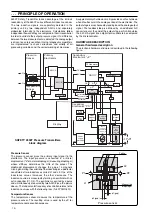
The total loop resistance is the sum of the resistance of all
elements of the loop, including wiring, conditioning
resistor,safety barriers and additional indicators (excluding the
equivalent resistance of the transmitter).
Where a configuration device (HART), such as the Hand Held
Communicator or a Modem is likely to be used, a resistance of
250 ohm minimum should be present between the power
supply and the point of insertion of these devices, to allow
communication.
Several types of safety barriers, either passive or active, can be
satisfactorily used in conjunction with the Smart 2600T
transmitters. Nevertheless, in case of use of active barriers,
check with the supplier if the model is suitable for use with
smart transmitters allowing the connection of the configuration
devices in the "safe" or non-hazardous area.
TRANSMITTER OUTPUT SIGNAL
The 2600T Safety transmitter provides both the analog 4
÷
20
mA and the digital HART communication. HART signals do not
affect safety during trading operations. HART writings are
permitted only in maintenance (out of safety) condition.
Analog Signal
Two-wire 4 to 20 mA dc, user-selectable for linear or square
root output; power of 3/2 or 5/2, 5th order or two 2nd order
switching point selectable programmable polynomial output
can be also selected for version with HART communication.
HART Signal
Digital process variable (%, mA or engineering units)
superimposed on the 4 to 20 mA signal, with protocol based on
Bell 202 FSK standard.
Output current limits (to NAMUR standard)
- Low saturation: 3.8 mA (field configurable from 3.5 to 4mA)
- High saturation: 20.5 mA (field configurable from 20 to 22.5 mA)
R (k
Ω
) =
Supply voltage - min. operating voltage (Vdc)
22.5
Transmitter failure mode (compliant to NE 43 NAMUR
regulation)
The output signal can be user-selected to a value of 3.7 or 22
mA on gross transmitter failure contition, detected by self-
diagnostics.
WARNING - The transmitter may be used as a
safety accessory (as defined by the Pressure Equipment
Directive 97/23/EC) i.e. as part of a shutdown system.
In this case it is recommended to select the correct fail
safe mode for the 4-20 mA signal (as per Namur NE43
recommendation).
See also the instructions relevant to fail safe selection
(Up/Down scale mode) in the addendum to the instruction
manual on "Use of hardware links on the secondary
electronics" .


