background image

- 42 -

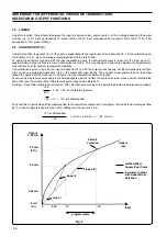
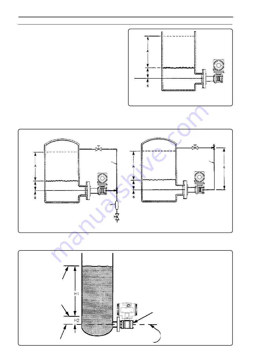
Max level

Minimum

level

Low side vented

Transmitter datum

Minimum level must be at or above this datum

Span

= H1*G1, in inches w.g. if H1 is in inches

G1

=  specific gravity of the process liquid

Lower range value = [H2*G1], in inches w.g. if H2 is in inches

Upper range value = Lower range value + span

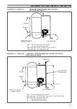
For a better understanding, three applications of liquid level measure are shown, as follows:

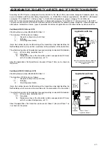
Application n

°

 1 : Liquid Level   - Open Tank

 Using a Flange-Mounted Transmitter

Max. level

Min. level

Datum

line

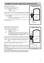
Dry leg

Gate valve

Condensate trap

(optional)

Wet leg

Gate valve

Datum

line

Min. level

Max. level

Filling tee

Figure 4 - Liquid level transmitter in closed tank installation

INSTALLATION WITH DRY LEG

INSTALLATION WITH WET LEG

In the closed tank application, Figure 4, the effect of tank pressure  is canceled by connecting the HI side and LO side of the primary
transducer to the tank. The HI side connection is made by mounting the transmitter on the tank nozzle. A compensating leg
connects to the LO side near the top of the tank. It is important to ensure that this leg is either completely free of liquid (dry leg)
or completely filled to a constant level (wet leg).

In  open tank applications, mounting the transmitter on the tank
nozzle provides the HI side process connection, with the LO
side being vented to atmosphere. The hydraulic head pressure
acting against the process diaphragm is a direct measurement
of the liquid level. The effect of atmospheric pressure is
canceled because this pressure is applied to both sides of the
transmitter.
A recommended open tank installation is shown in Figure 3.

. . . ADDENDUM FOR FLANGE-MOUNTED TRANSMITTERS

Figure 3 - Liquid level transmitter

in Open tank installation

Max. level

Datum

line

Min. level

S

N

O

S

S

T

I

U

C

R

I

C

S

E

L

N

O

I

N

E

T

S

O

S

T

U

R

R

E

V

U

O

C

E L

R E

D

R

A

G

T N

E

'

M

E

F

N

E

B

E

L

C

I

Q

U

A T

E

AL

S

T

I

U

C

RI

C

IVE

H

C O

P

E E

K

VER

TIG

T

E

H

W

N

!

S

N

O

S

S

T

I

U

C

R

I

C

S

E

L

N

O

I

N

E

T

S

O

S

T

U

R

R

E

V

U

O

C

E L

R E

D

R

A

G

T N

E

'

M

E

F

N

E

B

E

L

C

I

Q

U

A T

E

AL

S

T

I

U

C

RI

C

IVE

H

C O

P

E E

K

VER

TIG

T

E

H

W

N

!

S

N

O

S

S

T

I

U

C

R

I

C

S

E

L

N

O

I

N

E

T

S

O

S

T

U

R

R

E

V

U

O

C

E L

R E

D

R

A

G

T N

E'

M

E

F

N

E

B

E

L

C

I

Q

U

A T

E

AL

S

T

I

U

C

RI

C

IVE

H

C O

P

E E

K

VER

TIG

T

E

H

W

N

!

Summary of Contents for 268D/V

Page 1: ... 1 Operating instruction IM 268D_1 2600T Series Pressure Transmitters Models 268D V P ...

Page 2: ...vice and support worldwide We are committed to teamwork high quality manufacturing advanced technology and unrivalled service and support The quality accuracy and performance of the Company s products result from over 100 years experience combined with a continuous program of innovative design and development to incorporate the latest technology The NAMAS Calibration Laboratory No 0255 B is just o...

Page 3: ...absolute pressure flow and liquid level is provided in the even most difficult and hazardous industrial environments Now a Safety pressure Transmitter is included in the 2600T Series with its analog output signal plus HART digital communication The HART digital protocol allows remote re ranging calibration and diagnostics without any interference with the standard 4 20 mA analog output signal This...

Page 4: ...aximum process working pressure PS and tempera ture TS The instrument may be used as a safety accessory category IV as defined by the Pressure Equipment Directive 97 23 EC In this case near the CE mark there is the number of the notified body 0474 that verified the compliance Fig 1 Product identification Ref B Primary Unit TRANSPORT After final calibration the instrument is packed in a carton Type...

Page 5: ...lectronic Programmable Electronic System or software safety lifecycle phases of a Safety Instrumented System shall be identified All those specified as responsible for management of functional safetyactivitiesshallbeinformedoftheresponsibilitiesassigned to them All persons involved in any overall E E PES or software safety lifecycle activity including management activities should have the appropri...

Page 6: ...terface requirements Identification of the instrumentation for every physical risk property input and define their fail safe signal Definition of the required amount of instruments and certifications according the SIL requirements Identification of the type of actuator and definition of their fail safe position for the required safe action Definition of the required redundancy and certification Co...

Page 7: ...ent Functionality All the necessary activities to assure that the process sensor orfinalelementareoperatingtogetherandperformtherequired function are described in the Electrical connections and Calibration sections of the present document Overall System Functionality The activities to validate the required safety functionality of the system together with the target equipment according to the Safet...

Page 8: ... cleaning damage of the coating corrosion Other considerations The alarm levels of the transmitter down scale or up scale can be selected by the user For some faults e g crystal breakdown the output will latch at 22 mA even if the down scale alarm level is selected failure failure effect Comments p level measurement is wrong wrong measurement insensitive wrong measurement wrong measurement after c...

Page 9: ...cs to provide a proprietary standardized signal In the manufacturing process the sensor output characteristics are compared with reference pressures and temperatures the mapped parametersarethenstoredinthememoryofPrimary electronics Themeasuredvaluesandthesensorparametersaretransferred to the Secondary Unit where a microprocessor computes precise primary output linearisation compensating for the c...

Page 10: ...ignal to the electronics The input pressure is converted in a micro displacement d ofametaldiaphragm measuringdiaphragm whose stiffness determines the URL of the sensor The diaphragm displacement changes the gap of a magnetic circuit generatingthevariationoftheinductivepick updetector constituted of two inductances called L1 and L2 One of the inductance values increases the other decreases The ind...

Page 11: ...ns for the µP Power On Reset watchdog reset on ASIC7 request as described above and reset on power supply too low PWM Filter This first order RC filter gives an average value of the pulse width signal from ASIC 7 T5 Time Generator TheASIC7generatesatemperaturedependentcurrent applied to the T5 generation circuit that provides a time duration signal T5 used to measure the temperature in the seconda...

Page 12: ...s of the same mounting bracket Note for other installation details see the relevant Addendum WARNING The transmitter when installed in accordance with this instruction manual will not be subjected to mechanical stresses WARNING the transmitter should not be installed where it may be subjected to mechanical and thermal stresses or where it may be attached by existing or foreseable aggressive substa...

Page 13: ...ndum for details Fig 7 Location of the locking screws and terminals Grub screw ELECTRICAL CONNECTIONS The power to the transmitter is supplied over the signal wiring and no additional wiring is required The signal wiring does not need to be shielded but the use of a twisted pair is highly recommended The cable shield should be grounded in one side only to avoid dangerous earth paths WARNING For Ha...

Page 14: ...ons Fig 8c Electrical connections with remote indicator Line load GND Hand held communicator Power source Optional Receiver Test points 4 20 mA 250 ohm min Internal ground termination point 691HT A B C 1 D E F 2 G H I 3 J K L 4 M N O 5 P Q R 6 S T U 7 V W X 8 Y Z 9 0 PV REVIEW SERIAL LINK TRIM F1 F2 F3 F4 CONF External ground termination point M TEST COMM Line load GND Hand held communicator Power...

Page 15: ...sistor safety barriers and additional indicators excluding the equivalent resistance of the transmitter Where a configuration device HART such as the Hand Held Communicator or a Modem is likely to be used a resistance of 250 ohm minimum should be present between the power supply and the point of insertion of these devices to allow communication Severaltypesofsafetybarriers eitherpassiveoractive ca...

Page 16: ...t undesirable configuration changes by a dedicated hardwarelinkplacedonthesecondaryelectronicsboardwhich is identified as Write Protect Mode Link see fig 9 The following figure described the maintenance operating philosophy Table 1 WARNING After any configuration operation the transmitter must be put in operating condition as described in Table 1 During this change a software reset is performed an...

Page 17: ...s page ii the transmitter is properly powered and the electrical connections correctly made iii the Write Protect Mode link located on the electronics module is in position ON write allowed Access to the link is gained by unscrewing the secondary unit housing cover at the opposite end to the terminal cover See Fig 9 iv the Upscale Downscale link is positioned to the required function ON for Downsc...

Page 18: ...an b Usethezeroandspanprocedureabovebut apply pressures equal to the Lower Range Value LRV and then to Upper Range Value URV and turning for at least 1 second the zero and span screws respectively Absolute pressure Use the zero and span procedure as previously described but apply to the process connection absolute pressures equal to the Lower Range Value LRV and then to the Upper Range Value URV t...

Page 19: ...equested every 10 years The proof tests consists in the following operations 1 PuttheWriteProtectMode switchinWriteEnablecondition 2 Perform the Hart Command Change Transmitter status to Maintenance 3 Perform the Hart Command Clock monitor test The transmitter must go to up scale setting the secondary output stage To recover from the alarm status a power off power on operation is required 4 Power ...

Page 20: ...nd nuts and improper O rings can cause fractureoroverstressingofboltsandreleaseofpressurized processmaterial Useonlyofficialspareparts included in the supplementary documentation follow the reassembly procedure herebelow described and do not exceed the specified torque limits DO NOT REMOVE the O ring fitted in the sensor neck it provides the housing a degree of protection a Refit the flange fixing...

Page 21: ... electronics Electronics screw Blind cover Flange bolts Analog digital output indicator or CoMeter Extended windowed cover Blind cover Tang screw Terminal blocks assembly Sensor assembly Calibration screws Nameplate DISMANTLING AND REASSEMBLY ...

Page 22: ...inding checks before contacting your nearest Service Centre If the instrument is to be returned for repair ensure that it is adequately packed using the original polystyrene box or high density chipfoam thetroublesheet returningformshouldbesentwiththeinstrument filledinallitsparts Ifthetransmitterneeds to be dismantled follow the procedures as described in the previous section WARNING If the trans...

Page 23: ... 23 ...

Page 24: ...rinsic Safety type DO NOT REMOVE ANY COVER in areas classified as HAZARDOUS LOCATIONS CAN RESULTS IN HAZARD OF FIRE AND EXPLOSION Contact your Safety Dpt in order to establish correct installation procedure ADDENDUM FOR METERS OPTION OF THE TRANSMITTERS GENERAL DESCRIPTION This option provides three different indications meters inside the transmitter housing The output meters can be mounted on the...

Page 25: ... and the transmitter can be configured ProMeter is programmable only In the CoMeter in fact two are the main menu ConF METER and ConF XMTR ACCESS TO CONFIGURATION To enter these menù in both indicators the keys PREV and NEXT must be pressed simultaneously for 3 seconds then the user can switch between the XMTR and the METER configuration using the NEXT and the PREV key In the ProMeter entry is dir...

Page 26: ... Before accepting the transmitter configuration by pressing ENTER at the request ConF UPDATE it is possible to view the LRV ZERO the URV FULL SC and the UNIT If the output transfer function of the transmitter is not linear ProMeter and CoMeter show the message ConF NO_LIN and the user cannot update the configuration It is necessary to change the output transfer function of the transmitter to linea...

Page 27: ...er output so for security the loop should be put in Manual Use PREV or NEXT key to scroll through the options and ENTER key to change or view the values The procedure to change the numeric value remains the one already explained for PASSWORD operation i e the cursor starts blinking on the most significant digit then use the NEXT and PREV key to increase or decrease the value of the single digit th...

Page 28: ...4mA ENTER 04 000 04 000 04 000 ESC ENTER 04 000 04 000 REF VAL 4 000 REF TX ENTER SET20 mA ENTER ENTER 20 000 20 000 20 000 ESC ENTER 20 000 20 000 REF VAL 20 000 REF TX ENTER ENTER AUTO SET 4mA 4 001 TRIM ENTER ENTER NEXT PREV ENTER ENTER ENTER 0 050 KPA ESC ENTER ESC NEXT PREV ESC ESC ESC ESC ESC ESC NEXT PREV SET 20mA 20 000 TRIM ENTER ENTER ESC ESC NEXT PREV TO MODIFY DIGIT DECIMAL POINT MINUS...

Page 29: ...00 LRL ESC 40 000 URL ESC 1 0000 DAMPING ESC OUTPUT LIN ESC ENTER ESC NEXT PREV NEXT PREV Fig 8 PV menu ENG UNITS PV ENTER PRIMARY ESC ENTER 10 sec 10 690 KPA NEXT PREV or 8 280 mA 2ND 27 000 DEG C NEXT PREV ENTER or 26 750 3RD 10 000 MPA NEXT PREV ENTER 4TH 200 Lt min NEXT PREV ENTER NEXT PREV ESC ESC ESC 10 sec 10 sec ANALOG OUTPUT OUTPUT 10 sec 10 sec 10 sec ADDENDUM FOR COMETER OR INDICATOR WI...

Page 30: ... scaling for compensating scaling the reading for these 80 mbar The result of this operation is the transmitter s reading is now 0 mbar offset is 80 mbar and must be considered that while the limits of the transmitter remains LRL 400 mbar URL 400 mbar and the calibration does not change LRV 0 mbar URV 200 mbar The configuration tools allows you to evaluate the new operative limits operative LRL 48...

Page 31: ...EDURE See Fig 1 CAUTION This procedure should not be carried out on the field site a Remove the transmitter cover of the field connections side b Unplug the built in indicator if present c Unscrew the two Phillips screws M 4 x 18 mm which secure the terminal block and pull it off the housing d Unweld the and wires which connect the two RF radio frequency filters on the back of the terminal block e...

Page 32: ... indicator TERMINAL BLOCK Side Sect View Terminals to be welded into the specified holes TERMINAL BLOCK Front view SURGE PROTECTOR P C Board TERMINAL BLOCK Back view Self tapping screw M2 9x6 mm to secure the surge prot p c board Terminal holes to be used for welding the eyelet terminals of the RF Filter wires Two notches on the ext plastic case wall to lodge the surge prot p c board Self tapping ...

Page 33: ... fix the terminal block to the housing put the two wires in the position as shown above in order to avoid any damages Fig 2b Connection for terminal block and housing with surge protection Note Before to fix the terminal block to the housing put the two wires in the position as shown above in order to avoid any damages Black Red Green ...

Page 34: ...wer up the transmitter AFTER ANY REPLACE OPERATION IT IS RECOMMENDED TO MOVE DOWN IN 0 POSITION THE RELEVANT SWITCHES WRITE PROTECT mode With the switch 3 up in 0 position the write protect mode is active It is a way to protect the device from any change configuration data and parameters cannot be modified UP DOWN SCALE mode The switch 4 defines the fail safe output condition in case of transmitte...

Page 35: ...ut linearization using 2 polynomial functions of 2nd order Costant current for loop or associated equipment test where x and output are in the range 0 to 1 0 to 100 Figure 1 shows the Input output relationships with the different Square Root Options applied These output functions can be activated using a Configuration Tool like the Hand Held Communicator a HART Universal Communicator or a Personal...

Page 36: ...e programmable from 1 to 4 the output still varies linearly Then at input values greater then 4 the output follows the applied transfer function In the figure it is also indicated the default selection Toconvertfromapressurevaluewithinthecalibratedspantoapercentofflow firstexpressthepressureasapercentofcalibrated span then take the square root of this pressure percentage and multiply by 10 Example...

Page 37: ...elationship Using this function the output in of the span is proportional to the square root of the third power of the input signal in of the calibrated span the instrument e g gives an output proportional to the rate of flow calculated using the above mentioned formulas 4 0 SQUARE ROOT X5 This function can be used for open channel flow measurement using ISO 1438 V notch triangular weirs see Fig 4...

Page 38: ... the output Out normalized i e in the range 0 to 1 or 0 to 100 the vessel diameter corresponding to a circular area equal to 1 100 will be normalized by a K factor of the following value K 2 1 π 1 12838 The volume of the liquid contained in the vessel at heigth h will be V Out d 1 12838 2 L where d vessel diameter and L vessel length The non conformity error is within 0 1 between 0 5 and 99 5 of h...

Page 39: ...rcasesa tod andcalibratethe transmitterrangetocoverthefulldiameterofthevesselortank the changes in volume for the h changes between h0 and h max will be correct Of course the transmitter will transmit when the level is h0 thevolumecorrespondingtoh0 thesameapplyforlevel hmax All transmitted volumes are of the total volume of the vessel Ifitisrequiredthepartialvolumestartingfromh0 i e thevolumeath0 ...

Page 40: ...mials have to be calculated according to the shape of the vessel A PC based software tool is available for polinomial coefficients definition 7 0 CONSTANT CURRENT This output function activated by a Configuration Tool can be used to test the transmitter output the integrity of the transmission loop and the calibration of associated equipment like receivers recorders etc When this function is activ...

Page 41: ...nge of temperature ADDENDUM FOR FLANGE MOUNTED TRANSMITTERS The liquid level transmitter has been designed to connect to a flanged tank nozzle or similar ANSI DIN fitting Standard connections for 2 3 inch Class 150 300 600 flanges and equivalent DIN are available Flush and extended diaphragm options are also available Figure 2 The flush diaphragm is suitable for applications where the process is f...

Page 42: ...is important to ensure that this leg is either completely free of liquid dry leg or completely filled to a constant level wet leg In open tank applications mounting the transmitter on the tank nozzle provides the HI side process connection with the LO side being vented to atmosphere The hydraulic head pressure acting against the process diaphragm is a direct measurement of the liquid level The eff...

Page 43: ... H4 Gw in inches w g if H2 and H4 are in inches Upper range value Lower range value span G1 specific gravity of process liquid Gw specific gravity of liquid in wet leg Transmitter datum Minimum level must not be below this datum Max level Minimum level Span H1 G1 in inches w g if H1 is in inches G1 specific gravity of the process liquid Lower range value H2 G1 in inches w g if H2 is in inches Uppe...

Page 44: ... 7 0 0 2 7 8 7 0 0 2 6 4 8 5 1 2 5 0 9 0 3 2 6 6 8 0 2 2 5 2 9 5 3 2 1 7 0 8 1 1 7 0 8 1 6 8 0 2 2 2 0 1 6 2 1 7 0 8 1 1 7 0 8 1 6 8 0 2 2 2 0 1 6 2 1 7 0 8 1 6 8 0 2 2 9 7 0 0 2 9 7 0 0 2 2 0 1 6 2 1 1 8 2 9 7 0 0 2 4 9 0 4 2 1 1 8 2 6 2 1 2 3 9 7 0 0 2 4 9 0 4 2 7 3 0 5 9 7 3 0 5 9 7 3 0 5 9 7 3 0 5 9 7 3 0 5 9 7 3 0 5 9 7 3 0 5 9 7 3 0 5 9 7 3 0 5 9 7 3 0 5 9 4 4 4 4 8 8 8 8 8 8 g n i t a R e z...

Page 45: ... high value for FULL TRIM operation A standard operation must be performed according to the procedure If the result is not satisfactory the operation must be repeated with a procedure similar to that shown at point a above new calculated value with error taken with reversed sign Output Reranging Sometimes in case of tank level measurement it becomes difficult to calculate the LRV or the URV of the...

Page 46: ... i t a R g n i t a R e z i S e z i S e z i S e z i S e z i S n i m m s n o i s n e m i D n i m m s n o i s n e m i D n i m m s n o i s n e m i D n i m m s n o i s n e m i D n i m m s n o i s n e m i D f o N f o N f o N f o N f o N s e l o h s e l o h s e l o h s e l o h s e l o h a i d A a i d A a i d A a i d A a i d A a i d B a i d B a i d B a i d B a i d B a i d C a i d C a i d C a i d C a i d C...

Page 47: ...ther marking refers to the protection type used according to relevant EN standards Ex ia Intrinsic safety protection level a IIC Gas group T6 Temperature class of the transmitter which corresponds to 85 C max with a Ta ambient temperature 40 C About the applications this transmitter can be used in Zone 0 Gas and Zone 1 as it is shown on the picture According to ATEX Directive European Directive 94...

Page 48: ...a continuous hazard as it is shown on the picture Certificate ATEX II 1 2D Ex iaD 21 T95 C ZELM Certificate number ZELM 08 ATEX 0361 X The meaning of ATEX code is as follows II Group for surface areas not mines 1 2 Category D Dust dangerous media T95 C Maximum surface temperature of the transmitter enclosure with a Ta ambient temperature 75 C for Dust not Gas For application with dust layer betwee...

Page 49: ...the production of the transmitter The other marking refers to the protection type used according to relevant EN standards Ex tD A21 Construction with flameproof of protection method suitable for Dust Zone 21 About the applications this transmitter can be used in Zone 20 and Zone 21 Dust classified area continuous hazard as it is shown on the picture IP code About the degree of protection provided ...

Page 50: ...areas continuous hazard with its process part only whereas the remaining part of the transmitter i e its enclosure can be used in Zone 1 Gas only see sketch below Reason of this is the process part of the transmitter normally called primary transducer that provides inside separation elements to seal off the electrical sensor from the continuously hazardous process according to the EN50284 and EN50...

Page 51: ...I Division 1 Groups A B C and D hazardous classified locations Dust Ignition proof for Class II III Division 1 Groups E F and G hazardous classified locations Suitable for Class II III Division 2 Groups F and G hazardous classified locations NonIncendive for Class I Division 2 Groups A B C and D in accordance with Nonincendive field wiring requirements for hazardous classified locations Intrinsica...

Page 52: ...Electrical apparatus for explosive gas atmosphere Part 11 Intrinsic Safety i The 2600T Series pressure transmitters have been certified by CSA International for the following Class Divisions and Gas groups hazardous classified locations temperature class and types of protection Explosionproof for Class I Division 1 and 2 Groups A B C and D Class II Groups E F and G Class III Enclosure Type 4X Ex d...

Page 53: ... 53 ...

Page 54: ... 54 This page is intentionally blank ...

Page 55: ... oxygen transmitters and sensors ammonia nitrate phosphate silica sodium chloride fluoride dissolved oxygen and hydrazine analyzers Zirconia oxygen analyzers katharometers hydrogen purity and purge gas monitors thermal conductivity Customer Support We provide a comprehensive after sales service via a Worldwide Service Organization Contact one of the following offices for details on your nearest Se...

Page 56: ...15 674 7183 ABB SACE A division of ABB S p A Via Statale 113 22016 Lenno CO Italy Tel 39 0344 58111 Fax 39 0344 56278 ABB has Sales Customer Support expertise in over 100 countries worldwide www abb com instrumentation The Company s policy is one of continuous product improvement and the right is reserved to modify the information contained herein without notice Printed in Italy 07 2008 ABB 2008 ...

Reviews: