background image

2TMD042000D0050

  09.06.2021

Product manual

ABB-Welcome

M2241.-W Video Indoor Station 7

Summary of Contents for 2TMA210051W0001

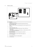
Page 1: ...2TMD042000D0050 09 06 2021 Product manual ABB Welcome M2241 W Video Indoor Station 7 ...

Page 2: ... 7 3 3 Dismantling 14 8 Commissioning 15 8 1 Operating instructions 15 8 2 Initial setup 16 9 Operation 21 9 1 Incoming call 21 9 1 1 Incoming call from outdoor station 21 9 1 2 Incoming call from indoor station guard unit 25 9 2 Surveillance 27 9 3 Intercom 29 9 4 Program button 30 9 5 History 31 9 5 1 Accessing the History screen 31 9 5 2 Displaying history records 32 9 5 3 Removing history reco...

Page 3: ...om list screen 53 10 3 2 Adding an intercom 54 10 3 3 Removing the intercom 56 10 4 Audio settings 58 10 4 1 Accessing the Audio settings screen 58 10 4 2 Setting the feedback tone 59 10 4 3 Setting the ringtone volume 60 10 4 4 Setting the ringtone type 61 10 5 Unlock password 63 10 6 Date and time settings 66 10 7 Display settings 68 10 8 Language setting 69 10 9 About 70 10 10 Restoring to fact...

Page 4: ...th live components This can result in electric shock burns or even death Disconnect the mains power supply prior to installation and or disassembly Permit work on the 100 240 V supply system to be performed only by specialist staff 3 Intended use This device is an integral part of the ABB Welcome door communication system and operates exclusively with components from this system The device must on...

Page 5: ...y 4 1 ABB devices All packaging materials and devices from ABB bear the markings and test seals for proper disposal Always dispose of the packing materials and electric devices and their components via an authorized collection facility or disposal company ABB products meet the legal requirements in particular the laws governing electronic and electrical devices and the REACH ordinance EU Directive...

Page 6: ...50 6 5 Product description 5 1 Device type Article number Product ID Product name Colour Size mm M22411 W 2TMA210051W0001 Video Indoor Station 7 White 184 2 x 137 6 x 19 M22413 W 2TMA210051W0002 Video Indoor Station 7 T loop White 184 2 x 137 6 x 19 ...

Page 7: ...dby status press to release the 2nd lock of the default outdoor station by default If multiple functions are set to the program button press to access the Program button screen 5 Mute button In standby status press to activate mute the ringtone In standby status long press to mute the ringtone of all indoor stations in the same apartment During a call request press to activate mute the ringtone an...

Page 8: ...veillance press to set the volume colour contrast and brightness 8 Microphone 9 Speaker Induction loop The induction loop is used for hearing impaired persons They can wear a hearing aid to hear the voice from the outdoor station or the indoor station The indoor station supports the hearing aids with T function and the maximum distance between them is around 35 cm ...

Page 9: ...ndoor station Only one indoor station in each apartment can be set as Primary ON Primary 5 Terminal resistor In video installations or mixed audio and video installations the switch must be set as RC on on the last device of the line ON RC on 6 Indoor station tens digit Adjust the jumper connector to set the tens digit of indoor station 0 9 7 Indoor station units digit Adjust the jumper connector ...

Page 10: ...ing voltage range 20 30 V Standby current 24 V 8 mA Operating current 24 V 290 mA Operating temperature 5 C 45 C Storage temperature 20 C 60 C Single wire clamps 2 x 0 28 mm2 2 x 0 75 mm2 Fine wire clamps 2 x 0 28 mm2 2 x 0 75 mm2 Product dimension WxHxD 184 2 x 137 6 x 19 mm IP level IP 30 ...

Page 11: ...edge and experience Incorrect installation endangers your life and that of the user of the electrical system Incorrect installation can cause serious damage to property e g due to fire The minimum necessary expert knowledge and requirements for the installation are as follows Apply the five safety rules DIN VDE 0105 EN 50110 1 Disconnect 2 Secure against being re connected 3 Ensure there is no vol...

Page 12: ...ormer or other power supplies to avoid interference Do not install the wires of the system bus together with 100 240 V wires Do not use common cables for the connecting wires of the door openers and wires of the system bus Avoid bridges between different cable types Use only two wires for the system bus in a four core or multi core cable When looping never install the incoming and outgoing bus ins...

Page 13: ...Mounting Installation Product manual 2TMD042000D0050 13 7 3 Mounting 7 3 1 Installation height 7 3 2 Surface mounted installation 1 50 m 4 9 feet 1 2 ...

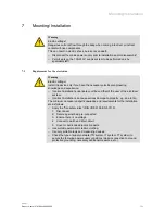
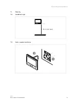
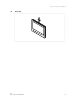
Page 14: ...Mounting Installation Product manual 2TMD042000D0050 14 7 3 3 Dismantling ...

Page 15: ... e g press to perform To switch the selection by pressing or the order of selection is from top to bottom and from left to right To switch the number quickly by holding or Press to carry out an operation like Enter the setting status Confirm the update value Go to next screen Press to carry out an operation like Exit the setting status Cancel the update value Go to previous screen ...

Page 16: ... 8 2 Initial setup You need to do the initial setup the first time this indoor station is powered on or this indoor station is reset to the factory defaults Please follow the steps below 1 Select the language A maximum of 17 languages for selection ...

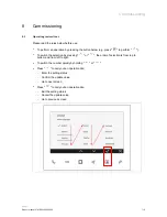
Page 17: ...Commissioning Product manual 2TMD042000D0050 17 2 Show the licence agreement ...

Page 18: ...42000D0050 18 3 Agree to the licence agreement 4 Set the date and time You can carry out this setting at this time or do it later by pressing Next to skip this setting For more details see chapter 10 6 Date and time settings on page 66 ...

Page 19: ...this time or do it later by pressing No to skip this setting For more details see chapter 10 1 Camera list on page 36 6 Set the program button You can carry out this setting at this time or do it later by pressing No to skip this setting For more details see chapter 10 2 Program button settings on page 47 ...

Page 20: ... 2TMD042000D0050 20 7 Set the intercom list You can carry out this setting at this time or do it later by pressing No to skip this setting For more details see chapter 10 3 Intercom settings on page 53 8 Complete the initial setup ...

Page 21: ...g status 2 Call ID 3 Display the rest of time 1 30 seconds The call request will be terminated if no operation is carried out within 30 seconds 4 Display the image from the calling outdoor station Note If you want to set the ringtone for the incoming call see chapter 10 4 4 Setting the ringtone type on page 61 Note During a call request if One on mode is used on the mini system controller only the...

Page 22: ...Operation Product manual 2TMD042000D0050 22 During a call request press to set the volume colour contrast and brightness ...

Page 23: ...on press to terminate the call During communication long press to take a snapshot This snapshot will be removed after 1 year No Description 1 indicates the communication status 2 Call ID 3 Display the rest of time 1 120 seconds 4 Display the image from the calling outdoor station ...

Page 24: ...Operation Product manual 2TMD042000D0050 24 During communication press to set the volume colour contrast and brightness ...

Page 25: ...request press to accept the call No Description 1 indicates the ring status 2 Call ID 3 Display the rest of time 1 30 seconds The call request will be terminated if no operation is carried out within 30 seconds Note If you want to set the ringtone for the incoming call see chapter 10 4 4 Setting the ringtone type on page 61 ...

Page 26: ...tion Product manual 2TMD042000D0050 26 2 Communication During communication press to terminate the call No Description 1 indicates the communication status 2 Call ID 3 Display the rest of time 1 120 seconds ...

Page 27: ...e press to activate the manual call During surveillance press to release the default lock of the outdoor station which is under surveillance During surveillance press to switch to the next image or terminate the surveillance No Description 1 indicates the surveillance status 2 Device ID to be monitored 3 Display the rest of time 1 15 seconds ...

Page 28: ...Operation Product manual 2TMD042000D0050 28 During surveillance press to set the volume colour contrast and brightness ...

Page 29: ...st needs to be added before use For more information see chapter 10 3 Intercom settings on page 53 Initiating an intercom Please follow the steps below 1 In standby status press to access the Intercom screen 2 Press the button below the designated intercom icon to initiate an intercom ...

Page 30: ... to be set before use For more information see chapter 10 2 Program button settings on page 47 Initiating a program function Please follow the steps below 1 In standby status press to access the Program button screen 2 Press the button below the designated program icon to initiate a program function ...

Page 31: ...on Product manual 2TMD042000D0050 31 9 5 History 9 5 1 Accessing the History screen Please follow the steps below 1 In standby status press 2 Select on the side menu 3 Press to access the corresponding screen ...

Page 32: ...ots means the record without snapshots means an incoming call from the outdoor station or an intercom call from other indoor stations or the guard unit means a surveillance or an intercom call to other indoor stations or the guard unit means a missed call 2 Press Note A maximum of 100 records can be saved Each record can include 2 snapshots and a maximum of 50 snapshots can be supported ...

Page 33: ...Operation Product manual 2TMD042000D0050 33 3 Display the date and time of the record 4 Display the device ID 5 Display the calling type 6 Press or to select the image ...

Page 34: ...Operation Product manual 2TMD042000D0050 34 9 5 3 Removing history records Please follow the steps below 1 On the History screen select the designated record 2 Press 3 Select 4 Press ...

Page 35: ...Operation Product manual 2TMD042000D0050 35 5 Press ...

Page 36: ...manual 2TMD042000D0050 36 10 Setting 10 1 Camera list 10 1 1 Accessing the Camera list screen Please follow the steps below 1 In standby status press 2 Select on the side menu 3 Press to access the corresponding screen ...

Page 37: ...ng Product manual 2TMD042000D0050 37 10 1 2 Creating a camera list Please follow the steps below 1 On the Camera list screen press to search for cameras 2 After a while a camera list is created successfully ...

Page 38: ...Setting Product manual 2TMD042000D0050 38 10 1 3 Renaming the camera Please follow the steps below 1 On the Camera list screen select the designated camera 2 Press 3 Select 4 Press ...

Page 39: ...Setting Product manual 2TMD042000D0050 39 5 Select a camera name 6 Press Note If the cameras use the same name they will be named with an incremented number e g Backdoor camera 1 Backdoor camera 2 etc ...

Page 40: ...Setting Product manual 2TMD042000D0050 40 10 1 4 Previewing the camera Please follow the steps below 1 On the Camera list screen select the designated camera 2 Press 3 Select Preview 4 Press ...

Page 41: ... 41 Warning message A warning message will be displayed on the screen when the designated outdoor station is busy Error message An error message will be displayed on the screen if the designated outdoor station is not detected by the system ...

Page 42: ...be displayed on the indoor station Note The Visual doorbell function can only be set when a camera is connected to the camera interface and this camera interface has been associated with the indoor station mode 4 Please see the camera interface product manual for more details Please follow the steps below 1 On the Camera list screen select the designated camera 2 Press ...

Page 43: ...Setting Product manual 2TMD042000D0050 43 3 Select 4 Press 5 will be displayed on the screen if successful 6 Press ...

Page 44: ...Setting Product manual 2TMD042000D0050 44 7 will be displayed on the screen to indicate the Visual doorbell status Note Only one camera can be set to Visual doorbell ...

Page 45: ...Setting Product manual 2TMD042000D0050 45 10 1 6 Removing the camera Please follow the steps below 1 On the Camera list screen select the designated camera 2 Press 3 Select 4 Press ...

Page 46: ...Setting Product manual 2TMD042000D0050 46 5 Press ...

Page 47: ...nual 2TMD042000D0050 47 10 2 Program button settings 10 2 1 Accessing the Program button screen Please follow the steps below 1 In standby status press 2 Select on the side menu 3 Press to access the corresponding screen ...

Page 48: ...uct manual 2TMD042000D0050 48 10 2 2 Adding a program function Please follow the steps below 1 On the Program button screen press 2 Select a function it can be set to 2nd lock Light Door Garage or Actuator 3 Press ...

Page 49: ...Setting Product manual 2TMD042000D0050 49 If the function is set to Light Door Garage or Actuator you need to select the address Note A maximum of 5 program functions can be set ...

Page 50: ...etting Product manual 2TMD042000D0050 50 10 2 3 Testing the program function Please follow the steps below 1 On the Program button screen select the designated program button 2 Press to test the function ...

Page 51: ...Setting Product manual 2TMD042000D0050 51 10 2 4 Removing the program function Please follow the steps below 1 On the Program button screen select the designated program button 2 Press 3 Select 4 Press ...

Page 52: ...Setting Product manual 2TMD042000D0050 52 5 Press ...

Page 53: ... manual 2TMD042000D0050 53 10 3 Intercom settings 10 3 1 Accessing the Intercom list screen Please follow the steps below 1 In standby status press 2 Select on the side menu 3 Press to access the corresponding screen ...

Page 54: ...anual 2TMD042000D0050 54 10 3 2 Adding an intercom Please follow the steps below 1 On the Intercom list screen press 2 Select the intercom type It can be set to Intercom internal Intercom external or Guard unit 3 Press ...

Page 55: ...Setting Product manual 2TMD042000D0050 55 4 Select the address 5 Press If the intercom type is set to Intercom internal you can skip step 4 5 Note A maximum of 5 intercoms can be set ...

Page 56: ...Setting Product manual 2TMD042000D0050 56 10 3 3 Removing the intercom Please follow the steps below 1 On the Intercom list screen press the designated intercom 2 Press 3 Select 4 Press ...

Page 57: ...Setting Product manual 2TMD042000D0050 57 5 Press ...

Page 58: ...t manual 2TMD042000D0050 58 10 4 Audio settings 10 4 1 Accessing the Audio settings screen Please follow the steps below 1 In standby status press 2 Select on the side menu 3 Press to access the corresponding screen ...

Page 59: ...g Product manual 2TMD042000D0050 59 10 4 2 Setting the feedback tone Please follow the steps below 1 On the Audio settings screen select Enable feedback tone 2 Press or to enable disable the function 3 Press ...

Page 60: ...ng Product manual 2TMD042000D0050 60 10 4 3 Setting the ringtone volume Please follow the steps below 1 On the Audio settings screen select Set ringtone volume 2 Press 3 Press or to adjust the volume 4 Press ...

Page 61: ...tting the ringtone type Please follow the steps below 1 On the Audio settings screen select Ringtone setting 2 Press 3 Select the designated device it can be Default outdoor station Other outdoor station Intercom Doorbell ringtone or Guard unit 4 Press ...

Page 62: ...Setting Product manual 2TMD042000D0050 62 5 Select the ringtone 6 Press ...

Page 63: ...ock password Note This function can only be set on the primary indoor station Please follow the steps below 1 In standby status press 2 Select on the side menu 3 Press Note The feedback tone will be enabled automatically when carrying out this setting ...

Page 64: ...Setting Product manual 2TMD042000D0050 64 4 Select Enable password and set the value to On 5 Select Enter password and press or to set the value for each digit one by one 3 8 digits ...

Page 65: ...Setting Product manual 2TMD042000D0050 65 6 will be displayed on the screen when the number of the digits reaches 3 7 Select Save 8 Press ...

Page 66: ...Date and time settings Please follow the steps below 1 In standby status press 2 Select on the side menu 3 Press 4 Press or to set the date 5 Press or to set the time Note It is recommended to correct your time once a year to ensure normal operation ...

Page 67: ...Setting Product manual 2TMD042000D0050 67 6 Press or to enable disable the Summer time function 7 Press or to enable disable the 24h function 8 Press ...

Page 68: ...roduct manual 2TMD042000D0050 68 10 7 Display settings Please follow the steps below 1 In standby status press 2 On the Settings screen select on the side menu 3 Press 4 Press or to adjust the brightness 5 Press ...

Page 69: ...Product manual 2TMD042000D0050 69 10 8 Language setting Please follow the steps below 1 In standby status press 2 On the Settings screen select on the side menu 3 Press 4 Press or to select the language 5 Press ...

Page 70: ...s below 1 In standby status press 2 Select on the side menu 3 Display the software version 4 Display the indoor station type Primary or Secondary 5 Display the indoor station address 6 Display the default outdoor station address 7 Scan the QR code to obtain the product manual ...

Page 71: ...Setting Product manual 2TMD042000D0050 71 10 10 Restoring to factory default Please follow the steps below 1 In standby status press 2 On the Settings screen select on the side menu 3 Press ...

Page 72: ...rence intrusion leakage and or theft of data or information ABB Ltd and its affiliates are not liable for damages and or losses related to such security breaches unauthorised access interference intrusion leakage and or theft of data or information Although ABB provides functionality testing on the products and updates that we release you should institute your own testing program for any product u...

Page 73: ...ed specifications agreed to at the time of ordering apply to all orders ABB accepts no responsibility for possible errors or incompleteness in this document We reserve all rights to this document and the topics and illustrations contained therein The document and its contents or excerpts thereof must not be reproduced transmitted or reused by third parties without prior written consent by ABB ...

Page 74: ...nt We reserve all rights to this document and the topics and illustrations contained therein The document and its contents or extracts thereof must not be reproduced transmitted or reused by third parties without prior written consent by ABB ABB Xiamen Smart Technology Co Ltd No 881 FangShanXiEr Road Xiang An Industrial Area Torch Hi Tech Industrial Development Zone Xiamen Tel 86 592 295 9000 Fax ...

Reviews: