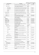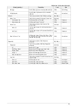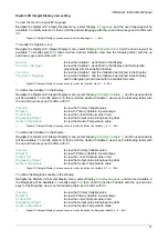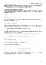
364Ax-Gx Instruction Manual
40
Trimming and Calibration Set Up
The calibration requires a stable Pressure Generator and a
Reference Pressure Indicator with the appropriate accuracy (at
least 4 time s better than the requi red accuracy of the
transmitter/measuring-chain).
The pneumatic circuit shall be verifie d to exclude connection
leakage problem or plugged lines.
The picture on the right show the complete test rigs that can
be selectively used to suit the calibration for th e Pressure
(gauge) and the Differential transmitters.
Before the calibration ensure that:
•
the required calibrated span (upper and lower range
values) is within the span and range limits (URL and LRL)
indicated on the nameplate
•
the transmitter is prope rly powered and the ele
ctrical
connections correctly made.
•
the write protect switch, located on the electronics module
is in position OFF (write allowed).
•
When making the connection, please ensure that there are
no residual fluids (for gaseous testing materials) or air
bubbles (for fluid testing materials) in the connection lines,
since they can lead to errors during inspection.
Make the electrical connections as indicated in th e picture.
Connect a precision milliammeter as shown and
remove the
short circuit link.
Sensor trim
The Sensor trim is a “set of operations, which establishes (by reference to standards) the relationship under
specified conditions, between a reference indication and a result of a measurement” (International
Vocabulary on Metrology).
In case the detected errors exceed the required accuracy, it is possible to correct the transmitter settings to
compensate these errors.
If the PV scaling has been performed the sensor trim is not available.
Reset the PV scaling before continuing the Sensor trim.
NOTE: If this cannot b e accomplished, the inst rument may require a fa ctory calibration or e ven its
substitution.
Sensor Zero Trim
The Sensor Zero trim provide the correct offset of the factory characterization. The transmitter shall be within
five percent of the true zero.
If the PV scaling has been performed the sensor trim is not available.
Reset the PV scaling before continuing the Sensor trim.
Sensor Zero trim by CoMeter
Sensor Zero trim by CoMeter is available with the 695 Field Indicator. Please refer to the device manual for
the appropriated operations.
Precision
Milliameter
Power Supply
10.5 to 42 V dc


