364Ax-Gx Instruction Manual
20
The relevant guidelines must be observed during the electrical installation!
The electrical connection may only be performed by authorized specialists according to the
electrical plans. Comply with electrical connection information in the manual. Otherwise, the elect rical
protection can be affected.
The 4 to 20 mA output signal and the dc power supply to the transmitter are carried from the same pairs of
wires. The supply voltage at the transmitter terminals must be between the limits of 10.5 and 42V dc.
For intrinsically safe approval Ex ia supply must not exceed 30 Vdc. In some countrie s the maximum power
supply voltage is limited to a lower value.
WARNING !
Electrical shock can result in death or serious injury. Avoid contact with the leads and terminals. High voltage
that may be present on leads can cause electrical shock.
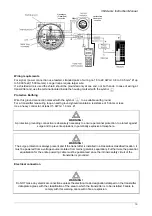
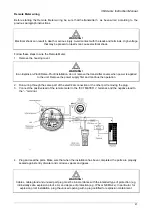
Follow these steps to wire the transmitter:
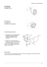
1. Remove the red temporary plastic plug from one of the two electrical connection ports located at both
sides on the top part of the transmitter housing
2. These connection ports have a ½ inch internal NPT or CM20 x 1.5 mm threads. Various adaptors and
bushings can be fitted to these threads to comply with plant wiring (conduit) standards.
3. Remove the housing cover.
WARNING !
In an Explosion-Proof/Flame-Proof installation, do not remove the transmitter covers when power is applied
to the unit. Remove the power supply and continue the operation
4. Run wires through the open port
5. Connect the positive lead to the + terminal, and the negative lead to the - terminal
WARNING !
Note: Do not connect the power across the test terminals. Power could damage the diode in the test
connection.
Plug and seal the electrical ports. Make sure that when the installation has been completed, the electrical
ports are properly sealed against entry of water and corrosive vapors and gases.
WARNING !
Cables, cable gland and unused port plug must be in accordance with the intended type of protection (e.g.
intrinsically safe, explosion proof, etc.) and degree of protection (e.g. IP6x or NEMA 4x). In particular, for
explosion proof installation, plug the unused opening with a plug certified for explosion containment.
6. If applicable, install wiring with a drip loop. Arrange the drip loop so that the bottom is lower than the
conduit connections and the transmitter housing.
7. Place the housing cover, screw it to fit O-ring into the housing and then continue to hand tighten until
the cover touch the housing metal-to-metal. In Ex d (Explosion Proof) installation, lock the cover rotation
by turning the set nut (use the 3 mm Allen key supplied with the instrument).
8. Replace the temporary red plastic plug on the second electrical connection port located in the upper
part of the transmitter housing with the appropriate plug depending on the certification requirement or
degree of protection (e.g. IP6x or NEMA 4x)
For further information find the rel evant instruction manuals searching for t he keyword “IM/*36* ” on
or from local ABB representatives.

