background image

364Ax-Gx Instruction Manual


73 


Back


Back


Back


Back


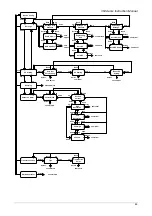
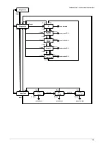
Diagnostics


Select

up

down

up

down

up

down

Hart Eng.

Output

up

Select

Output

Current

Output %

Select

Select

numerical RO

numerical RO

numerical RO

PV

down

Diagnostics


Select


Sensor

Temperature

Select

down

Back

Loop Test


Set


4 mA


Select


Select

auto adjust

auto adjust

Set

20 mA

Back


down/up

up


down

Back


Back


enumerated

numerical RO

up

Back


Select

manual adjust


Set


Custom Value


down/up

Back

up


down


Summary of Contents for 364A Series

Page 1: ...InstrumentationIT 2600T Pressure Transmitter family User s Manual 364Gx and 364Ax Models ABB IM364Gx Ax ...

Page 2: ...23 Easy Setup 23 HART Configuration 24 Basic Configuration Functions 24 Set the Damping 24 Set the Damping configuration by Digital LCD Integral Display 24 Set the Damping configuration by CoMeter 24 Set the Damping configuration by HHT 24 Set the Damping configuration by PC 24 Set the Units 24 Set the Units by Digital LCD Integral Display 24 Set the Unit by CoMeter ProMeter 25 Set the Unit config...

Page 3: ...ssing Communication data by Digital LCD Integral Display 38 Accessing Communication data by CoMeter 39 Accessing Communication data by HHT 39 Accessing Communication data by PC 39 Accessing Operation data 39 Accessing Operation data by Digital LCD Integral Display 39 Accessing Operation data by CoMeter 39 Accessing Operation data by HHT 39 Accessing Operation data by PC 39 Trimming and Calibration...

Page 4: ... 47 Safety information for Dismantling and Reassembly 47 Dismantling 48 Replacement 49 Electronics replacement 49 Data saving in case of replacement 49 Digital LCD Integral Display installation or replacement 49 Troubleshooting 50 Simple fault finding 50 Transmitter diagnostics 51 Diagnostic messages 51 Diagnostics on the Digital LCD Integral Display Hart version 51 Diagnostics on the CoMeter 52 H...

Page 5: ...ABB Instrumentation branches In case you fail to get in touch with your c ountry ABB Instrumentation office you may want to get in touch with one of the following center of excellence for ABB Pressure products ABB SpA Via Statale 113 22016 Lenno Co Italy Tel 39 0344 58111 Fax 39 0344 56278 ABB Automation Product GmbH Schillerstrasse 72 D 32425 Minden Germany Tel 49 551 905534 Fax 49 551 905555 ABB...

Page 6: ...binding warranty regulations in full The se contractual warranty provisions are neither extended nor limited by the information provided in this manual Caution Risk Only qualified and autho rized specialist personnel should be charged with installation electrical connection commissioning and maintenance of the transmitter Qualified personnel are persons who have experience in in stallation electri...

Page 7: ...ed Warranty provisions Using the device in a manner that do es not fall within the scope of its inte nded use disregarding this manu al using un der qualified personnel or making unauthorized alterations releases the manufacturer from any lia bility for any resulting damage This makes the manufacturer s warranty null and void Plates and symbols Danger Serious damage to health risk to life The appe...

Page 8: ...ironmentally friendly use of natural resources ABB conducts an open dialog with the public through its publications This product solution is manufactured from materials that can be reused by specialist recycling companies Information on WEEE Directive 2002 96 EC Waste Electrical and Electronic Equipment This product or sol ution is not subject to the WEEE Directive 2002 96 EC or corresponding nati...

Page 9: ...out can cause severe injuries Depressurize the pipeline tank before opening the transmitter connection Corrective maintenance work may only be performed by trained personnel Before removing the device depressurize it and any adjacent lines or containers Check whether hazardous materials have be en used as materials to b e measured before opening the device Residual amounts of hazardous substances ...

Page 10: ...mounting DPT 364 PV psi mA 12 006 mA 50 0 00290 Variable 1 Variable 2 Bar variable Tag units Menu start DPT 364 PV psi mA 12 006 mA 50 0 00290 Variable 1 Variable 2 Bar variable Tag units Menu start 11 1 2 3 4 5 6 7 8 9 10 12 13 14 15 14 14 14 14 15 15 Digital LCD display view NOTE The maximum value that the LCD can display is limited to 9999999 The decimal point is positioned automatically so tha...

Page 11: ...tent depending on the selected options Bracket kit Electrical connection blind plug Identification The instrument is identified by the data plates Nameplate The Nameplate provides information concerning the model cod e number maximum working pressure range and span limits power supply and output signal See code specification sheet for detailed information This plate also shows the transmitter seri...

Page 12: ... SST wire Handling The instrument does not require any special precautions during handling although normal good practice should be observed Storage The instrument does not require any special treatment if sto red as dispatched and within the specified ambient conditions Type 2 to ANSI ASME N45 2 2 1978 There is no limit to the storage period although the terms of guarantee remain as agreed with th...

Page 13: ...ved e g VDE VDI 3512 DIN 19210 VBG Elex V etc Measurement accuracy is largely de pendent on correct installation of the pre ssure transmitter and if applicable the related m easuring tube The m easuring setup should be as free as possible of critical ambient conditions such as major temperature variations vibration or shock Note If unfavorable ambient condition s cannot be avo ided owing to rea so...

Page 14: ...ng and maintenance Sealing and screwing in Connecting pin G B For sealing a flat gasket must be used in accordance with DIN EN 837 1 NPT threaded connector Seal the threads with Tape or another approved resistant sealant Reference to atmosphere for 364Gx For technical reasons it is necessary to apply atmospheric pressure to the reference side of the pressure sensor For this purpose there is a vent...

Page 15: ...stions for pipe mounting These suggestions shall not limit alternative solutions that the end user can define himself Horizontal pipe Vertical bracket Transmitter on the front Horizontal pipe Horizontal bracket Transmitter on up Vertical pipe Horizontal bracket Transmitter on the front ...

Page 16: ...364Ax Gx Instruction Manual 16 Vertical pipe Horizontal bracket Transmitter on up Vertical pipe Horizontal bracket Transmitter on the front Vertical pipe Horizontal bracket Transmitter on up ...

Page 17: ... to guarantee the best mechanical performances of the assembly 2 Tight the nuts f with the washers g below them in order to fix the bracket the torque value shall be 10 Nm 12 Nm Fix the Pressure transmitter using the two screws h in the package the torque value shall be 1 Nm 0 2 Nm Wall mounting In this chapter you can find suggestions for wall mounting These suggestions shall not limit alternativ...

Page 18: ... in the picture is strongly reccomended Digital LCD Integral Display positioning In case the optional i ntegral display meter is installed it is possibl e to mount the display in fo ur different positions rotated clockwise or counter clockwise with 90 steps This is possible by using one of the four connections located on the ba ck of t he display at a 90 angle each from the other Wiring HART hand ...

Page 19: ...nding connection is absolutely necessary to ensure personnel protection to protect against surge and to prevent explosions in potentially explosive atmosphere WARNING The surge protection is always present and if the transmitter is installed in a Hazardous classified location it must be powered from a voltage source isolated from mains galvanic separation Furthermore the potential equalization for...

Page 20: ...ower supply and continue the operation 4 Run wires through the open port 5 Connect the positive lead to the terminal and the negative lead to the terminal WARNING Note Do not connect the power across the test terminals Power could damage the diode in the test connection Plug and seal the electrical ports Make sure that when the installation has been completed the electrical ports are properly seal...

Page 21: ...e unit Remove the power supply first and continue the operation 2 Run wiring through the same port of the electrical connection or the other port removing the plug 3 Connect the positive lead of the remote meter to the EXT METER terminal and the negative lead to the terminal 4 Plug and seal the ports Make sure that when the installation has been completed the ports are properly sealed against entr...

Page 22: ...ectical input not used is replaced with a proper plug The cover is tightened up to metal to metal contact with the housing All the requirements are satisfied if the transmitter is working in hazardous area Apply power The transmitter will start up automatically at the power up If when using intrinsically safe transmitters an ammeter is connected to the output circuit or a modem is connected in par...

Page 23: ...grees Celsius g cm 2 grams per square centimeter inH2O F inches of water at 68 degrees Fahrenheit 20 C Kg cm 2 kilo grams per square centimeter inHg C inches of mercury at 0 degrees Celsius Pa pascal ftH2O F feet of water at 68 degrees Fahrenheit 20 C kPa kilopascal mmH2O F millimeter of water at 68 degrees Fahrenheit 20 C torr torr mmHg C millimeter of mercury at 0 degrees Celsius atm atmosphere ...

Page 24: ... Software Please refer to the Software instructions for the appropriate operations Set the Units To monitor t he process using the ap propriate units follow on e of the method s described in the next paragraphs Set the Units by Digital LCD Integral Display To change the unit in the Digital LCD Integral Display Navigate the Digital LCD Integral Display menu select Display Display Settings Display E...

Page 25: ... grams per square centimeter inH2O F inches of water at 68 degrees Fahrenheit 20 C Kg cm 2 kilo grams per square centimeter inHg C inches of mercury at 0 degrees Celsius Pa pascal ftH2O F feet of water at 68 degrees Fahrenheit 20 C kPa kilopascal mmH2O F millimeter of water at 68 degrees Fahrenheit 20 C torr torr mmHg C millimeter of mercury at 0 degrees Celsius atm atmosphere psi pounds per squar...

Page 26: ...ation for the seven digits and confirm with OK Note the minimum and the maximum values to select are indicated on the display Digital LCD Integral Display Keys sequence to set the LRV wihout pressure 2 1 2 2 Edit To set the Transmitter LRV with reference pressure Set the transmitter applie d pressure as for Lower Range value 0 Navigate the Digital LCD Integral Display menu select Device Config Rer...

Page 27: ... Integral Display Keys sequence to set the URV wihout pressure 2 1 2 3 Edit To set the Transmitter URV with reference pressure Set the transmitter applie d pressure as for Upper Range value 100 Navigate the Digital LCD Integral Display menu select Device Config Rerange Rerange with pressure Set URV 100 Select OK to start the autoadjust Digital LCD Integral Display Keys sequence to set the URV wih ...

Page 28: ... or to the Digital LCD Integral Display Transfer functions description Linear Using this function the relationship between the input measured value expressed in of the calibrated span and the output is linear i e at 0 input corresponds 0 output 4mA at 5 0 input corresponds 50 output 12mA and at 100 input corresponds 100 output 20mA Polynomial The polynomial function applied to the transmitter inpu...

Page 29: ...2 A3 x3 A4 x4 A5 x5 Double Poly Output B0 B1 x B2 x2 if x k Output C0 C1 x C2 x2 if x k Digital LCD Integral Display Keys sequence to set the Transfer Function 2 6 1 Edit In case one of the polynomial transfer function has been selected The existing polynomial coefficients in the transmitter will be used The coefficients can be set or modified only by HHT and PC Set the Transfer function on the tr...

Page 30: ...c This is possible directly by means of the transmitter without disconnect its electrical connection and without a 4 20 mA generator or a pressure generator Fixed output current by Digital LCD Integral Display To set 4 mA fixed output current Navigate the Digital LCD Integral Display menu select Diagnostics Loop Test Set 4 mA Confirm Digital LCD Integral Display Keys sequence to set 4 mA fixed out...

Page 31: ...il high i e output current 22 mA Software settings Write protect mode Changes can be prevented to the transmitter configuration data with the write protectio n electronics dip switch 2 If the transmitter write pr otection is activated the transmitter will not accept any writes to its memory Configuration changes such as trim and reranging cannot ta ke place In case the Digital LCD Integral Display...

Page 32: ... Display Keys sequence to set the Low saturation current 2 4 2 2 Edit To set Fail High current Navigate the Digital LCD Integral Display menu select Device config Output on alarm Set Fail Current Fail High Edit and the value change will be possible Select the desired value and confirm Digital LCD Integral Display Keys sequence to set the Fail High current 2 4 2 3 Edit To set Fail Low current Navig...

Page 33: ...agnostics section of this manual Navigate the Digital LCD Integral Display The Digital LCD Integral Display offers you an extensive range of functions which are grouped into menus to access the menu press the button below the display indication the bottom right icons on the Display to select the menu or submenus press the key close to the Select display indication bottom right position on the Disp...

Page 34: ...is function provides the transmitter rerange Sub Menu Rerange with pressure This function provides the transmitter rerange when a pressure source is available Sub Sub Menu Set LRV 0 Set the Low Range Value at the applied pressure Utility Auto Adjust Set URV 100 Set the Upper Range Value at the applied pressure Utility Auto Adjust Rerange no pressure This function provides the transmitter rerange w...

Page 35: ...et the bargraph variable Utility Enumerated Contrast Set the display contrast Utility Manual Adjust Display Settings This function has all the settings related with the variable on the display Sub Menu Display Eng unit This function set the display to show the Engineering unit Sub Sub Menu Pressure Set the display to show the Engineering unit of pressure Utility Enumerated Temperature Set the disp...

Page 36: ...performed Utility Numerical Reset to Factory Trim Set the output current Trim and the Sensor Trim at the Calibration performed in the factory during the trasmitter manufacturing Utility Enumerated Diagnostics This function provides all the Diagnostics information Main Menu Diagnostics This function provides all the Main Diagnostics information Sub Menu PV Monitor the PV value Utility Numerical HAR...

Page 37: ...e Primary Variable value Output to view th Primary Variable in percentage Current Out to view the current Output value in mA Engineering Output to view the Output value in Engineering Units Sensor Temperature to view the Sensor Temperature value Digital LCD Integral Display Keys sequence to modify the define the Variable 1 3 3 Edit To define the Variable 2 in the Display Navigate the Digital LCD I...

Page 38: ... protect the Display 3 8 1 Edit To change the Display Password The Display Password is a five digit string The default value at the transmitter delivery is This default password does not give the possibility to lock Navigate the Digital LCD Integral Display menu select Display Security Change Password and the current password will be available To modify select Edit then scroll the desired alphanum...

Page 39: ...al LCD Integral Display menu select Diagnostics Diagnostics scroll the submenu with the up and down keys select one of the following submenu PV to monitor the measured Primary Variable Hart Eng Output to access the Output value in Engineering Units Output Current to access the Output value in mA Output to access the Output value in percentage Sensor Temperature to access the measured sensor temper...

Page 40: ...rors during inspection Make the electrical connections as indicated in th e picture Connect a precision milliammeter as shown and remove the short circuit link Sensor trim The Sensor trim is a set of operations which establishes by reference to standards the relationship under specified conditions between a reference indication and a result of a measurement International Vocabulary on Metrology In...

Page 41: ...Display Keys sequence to Low Trim the sensor 6 1 1 Edit Sensor Low trim by HHT Sensor Low trim by Ha nd Held Terminal is available Please refer to the device manual for the right operations Sensor Low trim by PC Sensor Low trim by PC i s available using dedicated Software ABB can provide the references and the Software Please refer to the Software instructions for the right operations Sensor High ...

Page 42: ...in the Trimming and Calibration Set Up Using a precison milliamperometer read the current output Navigate the Digital LCD Integral Display menu select Calibrate Output Trim Set 4 mA and the value will be available To modify select Edit then scroll the desired value with the up a nd down keys and confirm with Next Repeat the operation for the seven di gits to have t he same reading of the milliampe...

Page 43: ... a stable value Navigate the Digital LCD Integral Di splay menu sele ct Device Config PV Scaling Auto Set Zero Scaling To accept the operation select OK and wait for the end a bargraph will indicate the working progress Digital LCD Integral Display Keys sequence to Auto Set Zero Scaling 2 2 1 OK As for method 2 Navigate the Digital LCD Integral Display menu select Device Config PV Scaling PV Scali...

Page 44: ...alue equal to the sum of the pressure to be elevated and the previous calibrated span Method 2 use the zero and span procedure above but apply pressures equal to the Lo wer Range Value LRV and then equal to the Up per Range Value URV press for at least 2 seco nd and release the Zero local adjustment key Z and Span local adjustment key S respectively The LRV pressure will be applied to the L ow Sid...

Page 45: ...ate the Digital LCD Integral Display menu select Device Config SW Write Protect To change the status of the Software write p rotection select Edit then Unlock and OK to remove the protection or Lock and OK to insert the protection Digital LCD Integral Display Keys sequence to Software Write Protect 2 7 Edit Software Write Protect by HHT Software write protection by Hand Hel d Terminal is available...

Page 46: ...hanical damage to the diaphragm i e due to pointed objects must be avoided Field update Each transmitter is label ed individually so it is imp erative that the app roval codes on each label match exactly during upgrade The label on the tran smitter reflects the replacement model code for reo rdering an assembled unit with the required communication protocol The 2600T Pressure transmitter Series al...

Page 47: ...e carried out in the listed orde r to avoid instrument damage See the pictures at the end of the instructions for better understanding Operation required tools 3 mm Allen key in the transmitter box Small Phillips screwdriver Small flat bladed screwdriver Safety information for Dismantling and Reassembly Read the following Safety information before to start any operation WARNING Only specialist per...

Page 48: ...y Data Sheet Dismantling Disassembling the transmitter is possible to inspect clean and repair it The Digital LCD Integral Display and Electronics dismantling are allowed See the Sectional vie w as reference Transmitter Sectional View for the 364 models without Digital LCD Integral Display Transmitter Sectional View for the 364 models with Digital LCD Integral Display ...

Page 49: ...y electronics when the 364XS is power cycled Digital LCD Integral Display installation or replacement To install the integral display 1 Look at the indication on the nameplate WARNING In an Explosion Proof Flame Proof installation do not remove the transmitter covers when power is applied to the unit 2 Remove the housing cover 3 Fit the Integral displ ay onto the se condary electronic At this purp...

Page 50: ...output is not in alarm condition Verify if 4 20 mA output trim is required Check for trapped gas in liquid lines and liquid in dry lines Check for sediment in process flanges Clear the electronics module connectors contact High low or irregular output current Replace the Electronics module Verify the output is between 4 and 20 mA or saturation levels Verify clean DC Po wer to transmitter Ma x AC n...

Page 51: ...s 5 Overrange The detected pressure is above the maximum static pressure MWP on the instrument nameplate Corrective actions 5 Sensor T Out Lim The sensor temperature is above 90 C or below 50 C Corrective actions 5 Current Out Satur The output is limited to the saturation limits but the measurement is beyond these limits The measured variable could be outside the configured span Corrective actions...

Page 52: ... process and ambient conditions e g pressure process temperature ambient temperature static pressure etc against the sensor and electronics limits If the conditions are close or outside the limits these improper i nstrument utilization can have seriously compromised the i nstrument functionality If the conditions are well inside the limits see the corrective actions of point 4 or 3 Diagnostics on ...

Page 53: ...364Ax Gx Instruction Manual 53 ...

Page 54: ...ce must be disposed of at a specialized recycling facility Do not dispose of the device in the municipal garbage Only privately used products may be disposed of in the municipal garbage according to the WEEE directive Note Proper disposal prevents negative effects on people and the environment and supports the reuse of valuable raw materials Materials See Technical data If it is not possible to di...

Page 55: ...n is provided on the name plate Type examination certificate Declaration of conformity For explosion protected models the EC type examination certificate or declaration of conformity must be observed and is part of this transmitter delivery Type of protection Intrinsically safe Ex ia Install only intrinsically safe devices in the transmitter signal circuit The signal circuit can be interrupted whi...

Page 56: ...sed i e in the case of ib supply the system takes over this level of protection The meaning of ATEX code is as follows II Group for surface areas not mines 1 2 Category It m eans that onl y a part of the tr ansmitter complies w ith category 1 and a second part complies with category 2 see picture on the right G Gas dangerous media D Dust dangerous media T85 C Maximum surface temperature of the tra...

Page 57: ... EN50284 and EN50018 About Dust application the transmitter is suitable for Zone 21 according to the EN 50281 as it is shown on the relevant part of pictures on the right Application with Gas Application with Dust Note the protection is mainly assured by the IP degree associated to the low power from the supply Certificate ATEX II 3G Ex nL IIC T6 and II 3D Ex tD A22 IP67 T85 C ZELM certificate num...

Page 58: ...61241 14 chapter 6 3 3 3 Note the number close to the CE marking of the transmitter safety label identifies the Notified Body which has responsibility for the surveillance of the production The other marking refers to the Intrinsic safety protection type used according to relevant EN standards Ex ia Intrinsic safety protection level a Ex iaD 20 Construction with inside intrinsic safety electronics...

Page 59: ...d types of protection Explosionproof for Class I Division 1 Groups A B C and D hazardous classified locations Dust Ignition proof for Class II III Division 1 Groups E F and G hazardous classified locations Suitable for Class II III Division 2 Groups F and G hazardous classified locations NonIncendive for Class I Division 2 Groups A B C and D in accordance with Nonincendive field wiring requirement...

Page 60: ...l apparatus CAN CSA E60079 11 02 Electrical apparatus for explosive gas atmosphere Part 11 Intrinsic Safety i The 2600T Series pressure transmitters have been certified by CSA International for the following Class Divisions and Gas groups hazardous classified locations temperature class and types of protection Explosionproof for Class I Division 1 and 2 Groups A B C and D Class II Groups E F and G...

Page 61: ...uding general purpose in an unclassified location The Transmitter can only be used according to this Protection Concept for the life of the product If more then one type of protection box on safety label are permanent marked the Pressure Transmitter must be removed from hazardous classified locations The selected Type of Protection is allowed to be changed only by manufacturer after a new satisfac...

Page 62: ... passive or a ctive can be satisfactorily used in conjunction with the 364 pressure transmitter models Nevertheless in case of use of active barriers check with the sup plier if the model is suitable for use with smart transmitters allowing the connection of the configuration devices in the safe or non hazardous area PED information integration Compliance with pressure equipment directive 97 23 EC...

Page 63: ...lable at www abb com searching for CORROSION pdf or from local ABB representatives Data of the table are based on information from manufacturers All data is based on a temperature of 20 C 70 F unless noted otherwise Since corrosion involves many more variables than this table considers such as trace contaminants aeration or temperature concentration profile stress corrosion cracking and pitting th...

Page 64: ...364Ax Gx Instruction Manual 64 ...

Page 65: ...364Ax Gx Instruction Manual 65 ...

Page 66: ...364Ax Gx Instruction Manual 66 Annex I Digital LCD Integral Display Menu Flow Chart ...

Page 67: ...ion Manual 67 up Exit Exit up up up up Exit Exit Exit Exit select select select select select select up Diagnostics Easy Setup Display Communication Calibrate Process display Device Config down down down down down down ...

Page 68: ...r Function Type Lin Point Easy Setup Pressure Polarity select next next next next Auto Set Zero Scaling Damping edit edit edit edit edit edit next next next next edit edit edit enumerated enumerated enumerated numerical enumerated numerical numerical auto adjust manual adjust next ...

Page 69: ...0 Back Select numerical Select numerical down up Select Auto Set Zero Scaling Select Select Select auto adjust numerical auto adjust manual adjust up down Select Select Failure Mode Select High Saturation back Select Low Saturation Fail High Select Select numerical enumerated Back Back Back Back Back Fail Low Select numerical numerical numerical up Set Fail Current PV Scaling Reset PV Scaling back...

Page 70: ...numerated Display Eng Unit back back back up down Display Settings down Select Select Select Select Select Select Select back up down Density Select back up down Level Select back up down Other Select back up down Custom Unit Select back down numerical numerical numerical numerical Display LRV 0 up down numerical numerical enumerated up down Select Select Select Display URV 100 Display Transfer Fu...

Page 71: ...truction Manual 71 Hart Tag Communication Select ASCII string Descriptor Select ASCII string Message Select ASCII string Polling Address Select enumerated Select Back Back Back Back down up down up down up down up ...

Page 72: ...lect Lower Sensor Trim Select down Back Back up down down numerical numerical Upper Sensor Trim Back up Output Trim Select Select Set 4 mA Select Back Back up down down numerical numerical Set 20 mA Back up up down Reset To Factory Trim up Back enumerated Select down up ...

Page 73: ...tput Current Output Select Select numerical RO numerical RO numerical RO PV down Diagnostics Select Sensor Temperature Select down Back Loop Test Set 4 mA Select Select auto adjust auto adjust Set 20 mA Back down up up down Back Back enumerated numerical RO up Back Select manual adjust Set Custom Value down up Back up down ...

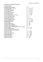
Page 74: ...saturation current 2 4 2 1 Edit to set the Low saturation current 2 4 2 2 Edit to set the Fail High current 2 4 2 3 Edit to set the Fail Low current 2 4 2 4 Edit to set the language 3 1 Edit to modify the Operator View 3 2 Edit to modify the define the Variable 1 3 3 Edit to modify the define the Variable 2 3 4 Edit to modify the define the Bargraph variable 3 6 to modify the define the Variable E...

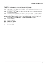
Page 75: ...ransmitter can be adjusted to measure URV Upper Range Value The highest value of the measured value to which the transmitter is calibrated LRV Lower Range Value The lowest value of the measured value to which the transmitter is calibrated SPAN The algebric difference between the Upper and Lower Range Values The minimum span is the minimum value that can be used without degradation of the specified...

Page 76: ... 50 dismantling safety 50 dismantling transmitter 51 E easy setup 24 electrical connections 20 electromagnetic compatibility 67 F failsafe direction change 34 fault simple finding 53 field update 49 fixed output current by cometer 33 fixed output current by hht 33 fixed output current by lcd 33 fixed output current by pc 33 function basic configuration 25 H handling 12 hardware settings 34 hazardo...

Page 77: ...ic trim 45 sensor static trim by hht 45 sensor static trim by pc 45 sensor trim 43 sensor trim zero 43 sensor trim zero by cometer 44 sensor trim zero by hht 44 sensor trim zero by pc 44 signal simulation 33 software settings 34 software write protect 48 software write protect by hht 48 software write protect by lcd 48 software write protect by PC 48 storage 12 T tranfer function linear 30 tranfer...

Page 78: ... Printed in Italy 09 2013 ABB 2013 IM 364GS_AS EN Rev C ABB ABB Ltd Howard Road St Neots Cambridgeshire PE19 3EU UK Tel 44 0 1480 475321 Fax 44 0 1480 217948 ABB Inc 125 E County Line Road Warminster PA 18974 USA Tel 1 215 674 6000 Fax 1 215 674 7183 ABB S p A Via Statale 113 22016 Lenno CO Italy Tel 39 0344 58111 Fax 39 0344 56278 ABB Automation Products GmbH Schillerstrasse 72 D 32425 Minden Ger...

Reviews: