LVD-EOMU02U-EN REVD 11/2022
10
—
3. Setup
Contents of this chapter
This chapter describes the how to configure the VFD-GATEWAY and drive parameter tables using the VFD-Gateway’s
built in web browser configuration pages.
3.1 Drive Setup
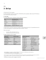
The VFD-GATEWAY supports the following drives and data connection sizes:
*With the ACS355 and ACH580 E-Clipse data mapping is handled differently than the ALL-Compatible drives due to a
number of fixed registers and will be illustrated further in sections 3.2 and 3.5.
Note, in this manual:
•
Read (In) is VFD to EtherNet/IP Network
•
Write (Out) is EtherNet/IP Network to VFD
3.2 Data mapping examples for ACS355
Drive
Supported data words
ACS355
9 words in / 3 words out*
ACS380
7 words in / out
ACH/Q/S580
7 words in / out
ACS880
12 words in / out
DCS880
12 words in / out
ACH580 E-Clipse bypass
9 words in / 3 words out**
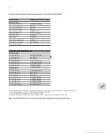
Drive Parameter
Example for ACS355
Setup parameters
10.01 Start Stop EXT 1
Comm
11.03 Speed Reference 1
Comm
11.04 Ref 1 Min
0 Hz
11.05 Ref 1 Max
60 Hz
98.02 Comm Protocol Select
STD Modbus**
53.02 Station ID
Drive 1,2..up to 5 *
53.03 Baud Rate
38.4 kbps**
53.04 Parity
8 EVEN 1**
ACS355 typical parameters
READ from VFD
Fixed word 4
Status Word
53.10 EFB Par 10
104 Motor Current
53.11 EFB Par 11
107 DC Bus Voltage
53.12 EFB Par 12
106 Motor Power
53.13 EFB Par 13
110 Drive Temp
53.14 EFB Par 14
1202 Constant Speed 1
53.15 EFB Par 15
1203 Constant Speed 2
53.16 EFB Par 16
1204 Constant Speed 3
53.17 EFB Par 17
1205 Constant Speed 4
53.18 EFB Delay***
0
30.18 Comm Loss
Warning
WRITE to VFD
Fixed word 1
Control Word
Fixed word 2
Ref 1
Fixed word 3
Ref 2
*58.03 Node Address corresponds to the VFD-GATEWAY Node Settings (see VFD-GATEWAY Settings Web Interface)
**The VFD-GATEWAY only supports these default settings
***It is recommended to set this to 0 to avoid adding delays to the data
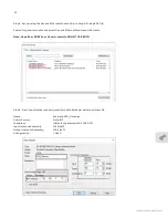
The first 4 registers are pre-mapped as Control Word, Ref 1, Ref 2, and Status Word. The next 8 registers can be customized as reads data.
Note: Every Parameter from 53.10-53.17 MUST contain a non-zero a value otherwise communication will not occur.
ACS355 must be power cycled for changes to take effect


