background image

7

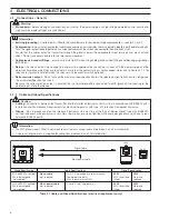
NC C NO

External

A.C. Supply

L

N

Relay Contacts

C

R

Load

A – A.C. Applications

NC C NO

External

D.C. Supply

+

Relay Contacts

Load

Diode

B – D.C. Applications

4

ELECTRICAL CONNECTIONS…

4.1.2

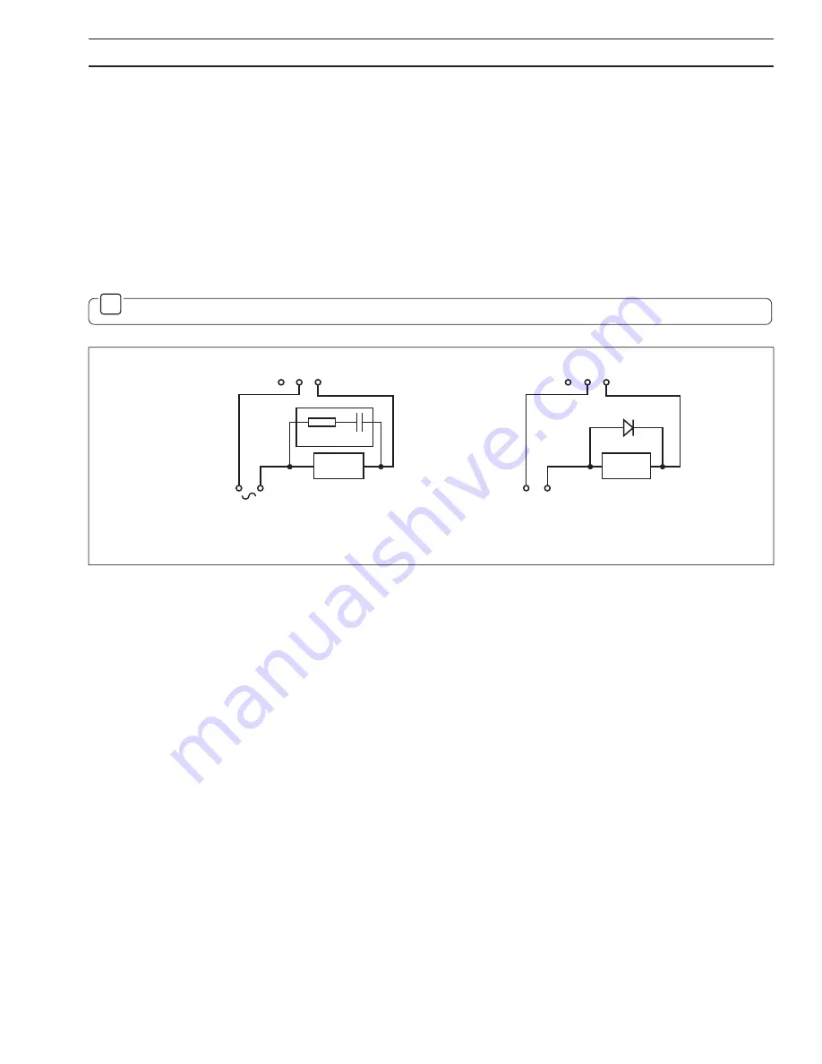
Relay Contact Protection and Interference Suppression – Fig. 4.1

If the relays are used to switch loads on and off, the relay contacts can become eroded due to arcing. Arcing also generates radio
frequency interference (RFI) which can result in instrument malfunctions and incorrect readings. To minimize the effects of RFI, arc
suppression components are required; resistor/capacitor networks for a.c. applications or diodes for d.c. applications. These
components can be connected either across the load or directly across the relay contacts. On 4600 Series instruments the RFI
components must be fitted to the relay terminal block along with the supply and load wires – see Fig 4.1

For 

a.c. applications 

the value of the resistor/capacitor network depends on the load current and inductance that is switched.

Initially, fit a 100R/0.022

µ

F RC suppressor unit (part no. B9303) as shown in Fig. 4.1A. If the instrument malfunctions (incorrect

readings) or resets (display shows 88888) the value of the RC network is too low for suppression an alternative value must be used.
If the correct value cannot be obtained, contact the manufacturer of the switched device for details on the RC unit required.

For 

d.c. applications 

fit a diode as shown in Fig. 4.1B. For general applications use a 1N5406 type (600V peak inverse voltage at 3A

– part no. B7363).

Note.

 For reliable switching the minimum voltage must be greater than 12V and the minimum current greater than 100mA.

Fig. 4.1 Relay Contact Protection

Summary of Contents for 4680

Page 1: ...Installation Operating Guide Models 4680 4685 EXFG Oxygen Transmitters 4600 4600 A1 A2 Oxygen 20 9 O x y g e n 25 0 A1 A2 ...

Page 2: ...nal conditions result in degraded process system performance leading to personal injury or death Therefore comply fully with all Warning and Caution notices Information in this manual is intended only to assist our customers in the efficient operation of our equipment Use of this manual for any other purpose is specifically prohibited and its contents are not to be reproduced in full or part witho...

Page 3: ...Panel mounted Instruments 3 3 MECHANICAL INSTALLATION 3 3 1 Siting Requirements 3 3 2 Mounting 4 3 2 1 Wall Pipe mounted Instruments 4 3 2 2 Panel mounted Instruments 5 4 ELECTRICAL CONNECTIONS 6 4 1 Connections General 6 4 1 1 Cable and Gland Specifications 6 4 1 2 Relay Contact Protection and Interference Suppression 7 4 2 Wall mounted Instrument Connections 8 4 3 Panel mounted Instrument Connec...

Page 4: ...oxygen content and temperature within a gas flue The 4680 500 model is a wall mounted instrument and the 4685 500 model is a panel mounted DIN sized instrument Signals from either transmitter can also be retransmitted to remote monitoring equipment Both models have a single programmable input channel and a single temperature input channel Instrument operation and programming is via four tactile me...

Page 5: ...L INSTALLATION 2 1 Checking the Instrument Type 2 1 1 Wall mounted Instruments Fig 2 1 2 1 2 Panel mounted Instruments Fig 2 2 3 1 Siting Requirements Fig 3 1 Caution Mount in a location free from excessive vibration Mount away from harmful vapors and or dripping fluids Information It is preferable to mount the instrument at eye level allowing an unrestricted view of the front panel displays and c...

Page 6: ...mounting plate Secure plates 1 2 3 4 A Wall mounting B Pipe mounting 68 2 68 214 8 43 232 9 13 Fixing Centres 160 6 3 250 9 84 69 2 72 Fixing Centres Allowance for Cable Bends 200 7 9 42 1 65 61 2 3 8 O D Vertical or Horizontal Post Dimensions in mm in 3 MECHANICAL INSTALLATION 3 2 Mounting 3 2 1 Wall Pipe mounted Instruments Figs 3 2 and 3 3 Fig 3 2 Overall Dimensions Fig 3 3 Mounting ...

Page 7: ...screws Loosen the retaining screw on each panel clamp Remove the panel clamp and anchors from the instrument case 4 5 6 1 3 2 3 191 7 52 12 0 47 Panel Cut out 96 3 78 96 3 78 0 8 0 92 3 62 0 03 0 0 8 0 92 3 62 0 03 0 Dimensions in mm in 3 MECHANICAL INSTALLATION 3 2 Mounting 3 2 2 Panel mounted Instruments Figs 3 4 and 3 5 Fig 3 4 Overall Dimensions Caution The clamp must fit flat on the instrumen...

Page 8: ...cables enter the transmitter through the glands nearest the appropriate screw terminals and are short and direct Do not tuck excess cable into the terminal compartment Cable glands conduit fittings ensure a moisture tight fit when using cable glands conduit fittings and blanking plugs bungs M20 holes Relays the relay contacts are voltage free and must be appropriately connected in series with the ...

Page 9: ...Series instruments the RFI components must be fitted to the relay terminal block along with the supply and load wires see Fig 4 1 For a c applications the value of the resistor capacitor network depends on the load current and inductance that is switched Initially fit a 100R 0 022µF RC suppressor unit part no B9303 as shown in Fig 4 1A If the instrument malfunctions incorrect readings or resets di...

Page 10: ...f Remove protection cover Slacken captive screws 1 2 3 4 2 4 ELECTRICAL CONNECTIONS 4 2 Wall mounted Instrument Connections Figs 4 2 and 4 3 Caution Slacken terminal screws fully before making connections Fig 4 2 Access to Terminals Wall mounted Instruments ...

Page 11: ...O Relay 1 Relay 2 N L Neutral Line Earth Earth Stud on case see Fig 4 2 NC C NO Normally Closed Common Normally Open Sleeved Links Cell retransmission input output from Interface Electronics Unit Rx Tx Receive Transmit 4 ELECTRICAL CONNECTIONS 4 2 Wall mounted Instrument Connections Figs 4 2 and 4 3 Fig 4 3 Wall mounted Instrument Connections Warning The power supply earth ground must be connected...

Page 12: ... Remove mains cover Mains Cover 1 2 4 ELECTRICAL CONNECTIONS 4 3 Panel mounted Instrument Connections Figs 4 4 and 4 5 Caution Slacken terminal screws fully before making connections Fig 4 4 Access to Terminals Panel mounted Instruments ...

Page 13: ...gic temperature alarm from Interface Electronics Unit Channel 1 Retransmission input output from Interface Electronics Unit Sleeved Links 4 ELECTRICAL CONNECTIONS 4 3 Panel mounted Instrument Connections Figs 4 4 and 4 5 Fig 4 5 Panel mounted Instrument Connections Warning The power supply earth ground must be connected to ensure safety to personnel reduction of the effects of radio frequency inte...

Page 14: ...15 115V 230V 115 4 Slide instrument out of case Undo captive screw Remove plug if fitted 1 2 3 4 ELECTRICAL CONNECTIONS 4 4 Selecting the Mains Voltage 4 4 1 Wall Pipe mounted Instruments Fig 4 6 4 4 2 Panel mounted Instruments Fig 4 7 Information Use a small flat bladed screwdriver to remove the screw cap from the case Fig 4 6 Selecting the Mains Voltage Wall Pipe mounted Instruments Fig 4 7 Sele...

Page 15: ...ed Parameter Value Adjust or Parameter X Y Z Select New value is automatically stored or 2 0 0 Oxygen Alarm LEDs Upper Display Line Lower Display Line Membrane Keys 5 CONTROLS AND DISPLAYS 5 1 Displays Fig 5 1 The display comprises a 5 digit 7 segment digital upper display line and a 16 character dot matrix lower display line The upper display line shows actual values of oxygen alarm set points or...

Page 16: ... E e c a f r e t n I e h t o t r e w o p s n i a m r o f o d e h c t i w s s i t i n U s c i n o r t c e l E e c a f r e t n I e h T e h t e d i s t u o f i h s a l f l l i w y a l p s i d r e p p u e h T t n e m u r t s n i e h t f o s t i m i l e h t e d i s t u o s i e u l a v n e g y x o d e r u s a e m e h T 5 2 o t 5 2 0 f o s t i m i l Oxygen The upper display indicates the measured oxygen ...

Page 17: ...on 7 1 Page 15 Set Up Outputs Page Section 7 3 Page 16 Operating Parameters 0 10 English Language Page Section 7 2 Page 15 Deutsch Francais Espanõl 00000 SECURITY CODE LANGUAGE PAGE English SET UP OUTPUTS Deutsch Francais Espanõl Fig 7 1 Overall Programming Chart Security Code Enter the required code number between 00000 and 19999 to gain access to the secure parameters If an incorrect value is en...

Page 18: ...ct YES for Logarithmic NO for Linear Retransmission Span Select the required retransmission span value in oxygen units from 5 25 to 25 00 Retransmission Zero Select the required retransmission zero value in oxygen units from 0 25 to 20 00 Test Retransmission The instrument automatically transmits a test signal of 0 25 50 75 and 100 of the retransmission range selected above The test signal selecte...

Page 19: ...ial Analytics Instrumentation pH conductivity and dissolved oxygen transmitters and sensors ammonia nitrate phosphate silica sodium chloride fluoride dissolved oxygen and hydrazine analyzers Zirconia oxygen analyzers katharometers hydrogen purity and purge gas monitors thermal conductivity Customer Support We provide a comprehensive after sales service via a Worldwide Service Organization Contact ...

Page 20: ...ined herein without notice Printed in UK 08 02 ABB 2002 ABB Limited Oldends Lane Stonehouse Gloucestershire GL10 3TA UK Tel 44 0 1453 826 661 Fax 44 0 1453 827 856 ABB Inc 2175 Lockheed Way Carson City NV 89706 USA Tel 1 0 775 883 4366 Fax 1 0 775 883 4373 ABB has Sales Customer Support expertise in over 100 countries worldwide www abb com ...

Reviews: