- 4 -
OPERATIVE LIMITS
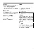
The transmitter operates on a minimum voltage of 10.5 Vdc to
a maximum of 55
Vdc and is protected against polarity
inversion.
Note - The transmitter operates from 10.5 to 42
Vdc with no load (a load up to 620
Ω
allows operation
up to 55 Vdc). For EEx ia and intrinsically safe (FM,
CSA and SAA) approval power supply must not
exceed 30 Vdc.In some countries the maximum
power supply voltage is limited to a lower value.
Installing optional devices the minimum voltage increases to:
- 10.5 Vdc with no option or with integral digital display
- 10.7 Vdc with output analog indicator
- 12.5 Vdc with output LCD indicator
- 12.1 Vdc with surge protection
- 14.1 Vdc with LCD indicator and surge protection
- 13.1 Vdc with LCD CoMeter
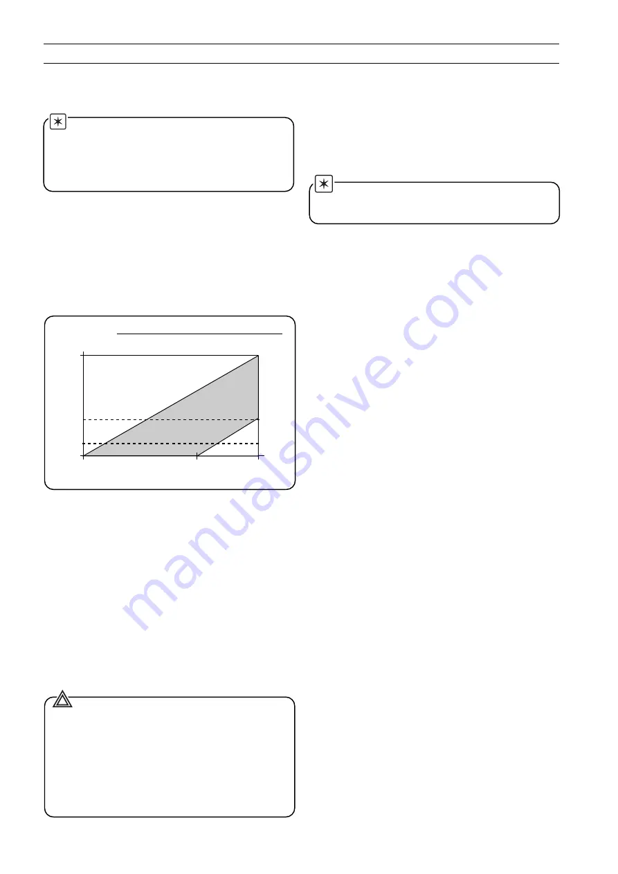
The total loop resistance is indicated in the figure and
expression below.
The total loop resistance is the sum of the resistance of all
elements of the loop, including wiring, conditioning resistor,
safety barriers and additional indicators (excluding the
equivalent resistance of the transmitter).
Where a configuration device (HART), such as the Hand Held
Communicator or a Modem is likely to be used, a resistance of
250 ohm minimum should be present between the power
supply and the point of insertion of these devices, to allow
communication.
Several types of safety barriers, either passive or active, can be
satisfactorily used in conjunction with the Smart 600T EN
transmitter. Nevertheless, in case of use of active barriers,
check with the supplier if the model is suitable for use with
smart transmitters allowing the connection of the configuration
devices in the "safe" or non-hazardous area.
WARNING - The transmitter may be used as a
safety accessory (as defined by the Pressure Equipment
Directive 97/23/EC) i.e. as part of a shutdown system.
In this case it is recommended to select the correct fail safe
mode for the 4-20 mA signal (as per Namur NE43
recommendation).
See also the instructions relevant to fail safe selection (Up/
Down scale mode) in the addendum to the instruction
manual on "Use of hardware links on the secondary
electronics" .
R (k
Ω
) =
Supply voltage - min. operating voltage (Vdc)
22
Supply voltage
Total loop resistance 250
(ohms)
2020
25 (ref.)
10.5
55 (volts)
42
4 to 20 mA and
HART digital communication
620
4 to 20 mA only
600
Temperature limits
°
C (
°
F) :
• Ambient (is the operating temperature)
All models and sensors can withstand without damages or
leakages temperatures from -40 to +85
°
C, -40 to +185
°
F.
-20
°
C, -4
°
F for Viton gaskets.
See the instrument data sheets for temperature effect on
response time and accuracy.
Note: For Hazardous Atmosphere application see the
temperature range specified on the certificate/approval
relevant to the aimed type of protection.
• Process (1)
Lower limit
- refer to lower ambient limits
- -20
°
C (-4
°
F) for Viton gaskets
Upper limit
- Silicone oil and KTFILL-1 filling : 120
°
C (248
°
F) (2)
- Inert fluid filling : 100
°
C (212
°
F) (3)
(1) Process temperature above 85
°
C (185
°
F) requires derating the
ambient limits by 1.5 : 1 ratio.
(2) 100
°
C (212
°
F) for application below atmospheric pressure
(3) 65
°
C (150
°
F) for application below atmospheric pressure
Pressure Limits
For model number see the first five characters of Product
Code on label Ref. A.
The sensor code is the sixth character.
• Lower : 0.067 kPa abs, 0,67 mbar abs, 0.01 psia
(0.13 kPa abs, 1.33 mbar abs, 0.02 psia for sensor code A).
Double the lower limit with inert filling
• Upper
- model 6X1ED, EG, EA
sensor codes B to W : 14 MPa, 140 bar, 2030 psi
sensor code A : 8 MPa, 80 bar, 1160 psi
sensor code U : 25 MPa, 250 bar, 3620 psi
- model 6X1EE :
all sensor codes : 25 MPa, 250 bar, 3620 psi
- model 6X1EH :
all sensor codes :1 MPa, 10 bar, 145 psi
- model 622ED :
sensor codes R, E, F : 42 MPa, 420 bar, 6090 psi
sensor code L : 32 MPa, 320 bar, 4640 psi
- model 6X1ES
10 MPa, 100 bar, 1450 psi or the following flange/fitting
rating of the seal, whichever is less.
• flanged seals (S6E/S6F)
ANSI CL 150 : 2 MPa, 20 bar, 290 psi
ANSI CL 300 : 5 MPa, 50 bar, 725 psi
ANSI CL 600 : 10 MPa, 100 bar, 1450 psi
ANSI CL 900 : 16 MPa, 160 bar, 2320 psi
DIN ND 16 : 1.6 MPa, 16 bar, 230 psi
DIN ND 40 : 4 MPa, 40 bar, 580 psi
DIN ND 64 : 6.4 MPa, 64 bar, 930 psi
DIN ND 100 : 10 MPa, 100 bar, 1450 psi
DIN ND 160 : 16 MPa, 160 bar, 2320 psi
• sanitary seals (S6S)
2in Triclamp : 3.8 MPa, 38 bar, 550 psi
3in Triclamp : 2.4 MPa, 24 bar, 350 psi
4in Triclamp : 1.7 MPa, 17 bar, 250 psi
F50/F80 Union nut : 2.5 MPa, 25 bar, 360 psi
Summary of Contents for 6X1ED
Page 6: ... 6 CORROSION TABLE ...
Page 7: ... 7 CORROSION TABLE ...
Page 8: ... 8 CORROSION TABLE ...
Page 9: ... 9 CORROSION TABLE ...
Page 14: ... 14 ...
Page 16: ... 16 PED600TEN Rev 1 ...

