background image

Model 8242
Colorimetric Phosphate Monitor

Instruction Manual

All Versions

OUT OF SERVICE

ALARM 1

CAL

ALARM 2

HOLD

OUT OF SAMPLE

Phosphate 8242

Summary of Contents for 8242

Page 1: ...Model 8242 Colorimetric Phosphate Monitor Instruction Manual All Versions OUT OF SERVICE ALARM 1 CAL ALARM 2 HOLD OUT OF SAMPLE Phosphate 8242 ...

Page 2: ...onditions result in degraded process system performance leading to personal injury or death Therefore comply fully with all Warning and Caution notices Information in this manual is intended only to assist our customers in the efficient operation of our equipment Use of this manual for any other purpose is specifically prohibited and its contents are not to be reproduced in full or part without pr...

Page 3: ...ns 25 8 1 1 Reagent Solution 25 8 1 2 Standard Solutions 25 8 1 3 Rinse Solution for Internal Pipework 25 8 2 Scheduled Servicing 26 8 2 1 Regular Visual Checks 26 8 2 2 Five weekly 26 8 2 3 Twelve monthly 26 8 2 4 Rinsing Internal Pipework 27 8 2 5 Consumable Spares Kit see Section 10 27 8 2 6 Peristaltic Pump 27 8 2 7 Replacement of Plumbing Tubing 27 8 3 Shutdown Procedure 27 8 4 Unscheduled Se...

Page 4: ... valve is then used to select automatically one stream to be sampled sequentially This allows sample under controlled pressure conditions to be c presented to a multi channel peristaltic pump which d proportions sample and reagent through a series of mixing and reaction stages The reaction stage is temperature controlled to remove the effects of sample and ambient temperature variations e The reac...

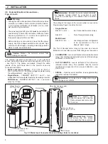
Page 5: ...tronics section follow steps 1 to 3 To gain access to the liquid handling section follow steps 4 and 5 Mains ON OFF Switch 5A Fuse HOLD Switch Pump ON OFF Switch Cable Glands Unscrew and swing out to see the connector blocks Internal view of liquid handling section Pump Motor Solenoid Valves Mixer Assembly Stirrer Motor Delay Coil Inside Heated Reaction Block Pinch Valve Contaminated Drain Tundish...

Page 6: ...ng caps 1 x spares kit 2 2 Location Install in a clean dry well ventilated and vibration free location giving easy access and where short sample lines can be used Avoid rooms containing corrosive gases or vapors e g chlorination equipment or chlorine gas cylinders It is also advisable to have adjacent drains near ground level so that the waste outlet from the monitor can be as short as possible to...

Page 7: ...be hose connector the larger of the two tube connectors 1 2 3 4 2 INSTALLATION Notes Use tube of inert material e g p v c The sample inlet tube must incorporate a shut off valve at its up stream end Ensure the drain outlet tube is short has a free fall and is vented to atmosphere as soon as possible Fig 2 2 External Pipe Connections Information To gain access to the constant head assembly follow s...

Page 8: ...r see Fig 2 3 Single Stream CURRENT OUTPUT 1 and 2 two independent current outputs for external recording or control Multi Stream CURRENT OUTPUT 1 to 6 one current output per stream Information Because the current output is isolated the negative terminal MUST be connected to earth ground if connecting to the isolated input of another device The setting of the range of the current output is covered...

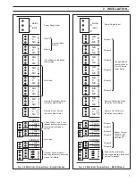
Page 9: ...O P 2 O P 3 O P 4 O P 5 O P 6 Power Supply Input Stream 1 Stream 2 Stream 3 Stream 4 Stream 5 Stream 6 Configurable as concentration or Out of Sample Alarm Relay Remote Calibration Mode Indication Alarm Relay Remote Out of Service Indication Alarm Relay Stream 1 Stream 2 Stream 3 Stream 4 Stream 5 Stream 6 Stream Current Outputs one current output per stream Optional Serial Interface see supplemen...

Page 10: ...d For d c applications fit a diode as shown in Fig 2 6B For general applications use an IN5406 type 600 V peak inverse voltage at 3 A part number B7363 Note For reliable switching the minimum voltage must be greater than 12 V and the minimum current greater than 100 mA Note Before proceeding any further ensure that the HOLD switch is ON all other switches are set to OFF on the right hand side of t...

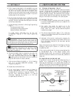
Page 11: ...olor compensation is required switch to Enable for manual compensation only or to automatic timed compensation by selecting a frequency between 1 to 24 hours using Programming Page 3 3 For general information regarding the setting up of the color compensation see Section 7 2 4 1 Principle of Operation Fig 4 1 The chemical method used in the monitor utilizes the reaction between orthophosphate moly...

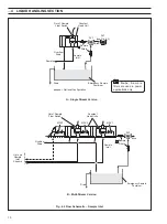
Page 12: ... 3 2 1 Up to six Sample Inlet Streams Out of Sample Float Switch Constant Head Unit Overflow Drain Sample Inlet SV3 Drain Emergency Sample Container Sample Blue Optional Configuration SV1 see Fig 4 3 A Single Stream Version B Multi Stream Version 4 LIQUID HANDLING SECTION Fig 4 2 Flow Schematic Sample Inlet N o t e S a m p l e filters are used in power applications only ...

Page 13: ...istaltic pump via valve SV5 in the multi stream version the sample is passed directly to drain This is important because bubbles in the sample will give variable reagent mixing resulting in noisy readings on the display The reagent solution delivered via one channel of the pump is then added to the sample before entering the dynamic mixer block and then passes through the heated delay coil where t...

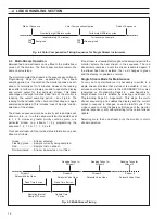
Page 14: ...uld be normally set to sample each stream in turn i e on a three stream version this would be set to 1 2 3 However greater priority could be given to a particular stream e g stream 1 by programming the sequence 1 2 1 3 or 1 1 1 2 3 etc Front panel stream LEDs provide status information on each stream as follows Green Stream selected Flashing green Sample currently being sampled Red Sample lost on ...

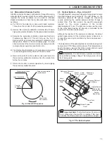
Page 15: ... be noted e Remove the tube from the container rinse and return it to the secondary calibration container Run the monitor for a further five minutes f Return the monitor to normal operation by de energizing the secondary calibration valve 4 5 Optical System Figs 4 6 and 4 7 The optical system comprises a tungsten halogen exciter lamp mounted between two photocells The light falling on the measurin...

Page 16: ... the Out of Service relay and inhibit any timed automatic calibrations 5 2 Display The monitor display panel indicates the solution concentration and provides user information during setting up and in normal operation 5 3 L E D Indicators Out of Service Indicates that the monitor out of service alarm is active the source is indicated on Programming Page 1 0 see Section 6 Cal Indicates when a calib...

Page 17: ...rsor or stepping up or down through a selection of parameters applicable to a particular function Cursor Used to step through the parameters within a page The selected values flash Sub page Advance Used for advancing through sub pages e g to advance from Program Page 1 3 to 1 4 Liquid Crystal Display LED Indicators See Section 5 3 for functions 5 ELECTRONICS SECTION Fig 5 1 Front Panel Controls Si...

Page 18: ...s the user terminations alarm relays and sockets for the four plug in boards Cuvette Input Board Processes the signals from the two photocells and controls the lamp brightness Microprocessor Board The heart of the electronics section which controls all aspects of the monitor Drive Board Provides outputs to drive internal functions i e stream section calibration valves pump motor and heater control...

Page 19: ...ump and Heater Drive Board Microprocessor Board Cuvette Input Board Pump ON OFF Switch HOLD Switch Lamp Drive Photocell Meas Photocell Ref PT100 1 PT100 2 1 2 3 4 5 6 Out of Sample Out of Reagent Stream Solenoids Drain Secondary Auto Zero Color Compensation Emergency Display Keypad Board Pump 2 Pump 1 Stirrer Heater 2 Heater 1 1 2 3 4 5 6 5 ELECTRONICS SECTION Fig 5 4 Electronics Schematic ...

Page 20: ...y xxx Color comp applied x units Color comp date DD MM YY xx xx xx Color comp time HH MM xx xx AUTO ZERO SEQUENCE PAGE 2 4 Reading xxx units Time to compensation xx min Abort AZ calibrations NO SECONDARY CAL NO SECONDARY CALIBRATION SEQUENCE PAGE 2 5 Reading xxx unit Time to compensation xx min Abort SEC calibrations NO SAMPLE RECOVERY SEQUENCE PAGE 2 6 Reading xxx units Time to end of sequence xx...

Page 21: ...x units Lamp alignment V read x xxx Volts Lamp alignment V ref x xxx Volts Alter factory settings security code xxxx ELECTRICAL CALIBRATION PAGE 6 4 Temperature chan1 zero 100 xxx x Temperature chan1 span 150 xxx x Temperature chan2 zero 100 xxx x Temperature chan2 span 150 xxx x ELECTRICAL CALIBRATION PAGE 6 5 Current output 1 4mA Current output 1 20mA Current output 2 4mA Current output 2 20mA F...

Page 22: ...ibration is disabled then OFF is displayed in place of the date The date of the last SECONDARY calibration Enter the value of the previously entered security code Set the following three parameters to YES when the tasks are carried out Once set to YES change the display on Page 0 to the required value Sets the date of the next 5 weekly service Sets the date of the next yearly service Used during r...

Page 23: ...ion factor value is maintained Reading during recovery back onto the sample The display shows the reading which incorporates new calibration values Remaining time to end of sequence See Programming Page 1 1 To abort the sequence set to YES Displays number of Drain Fill counts before color compensation See Programming Page 6 8 Displays number of Drain Fill counts before the end of the color compens...

Page 24: ... can be delayed in the event of the alarm condition If the alarm condition clears within the programmed delay time the alarm function is not activated and the delay time is reset Set the required delay time in the range 0 to 99 minutes in 1 minute increments A differential set point can be set as a percentage of the set point value The differential setting operates on the set point Example a 5 dif...

Page 25: ...e 20min increased if the sample value is near zero Enables the acceptable range of zero offset to be selected before a calibration fail alarm is initiated 0 6 to 30 as PO4 3 or 0 2 to 10 as P OFF normally set to 6 as PO4 3 2 as P Enables the acceptable range of calibration factor to be selected before a calibration fail alarm is initiated 0 15 to 0 5 OFF normally set to 0 2 Set the fill drain cycl...

Page 26: ...ELINE AUTO ZERO a SECONDARY calibration is initiated Subsequent timed ROUTINEAUTO ZEROs generate a new zero offset value which can then be assessed to check for zero drift within the life of the reagent normally five weeks If the zero offset is outside factory pre set limits a calibration fail alarm is initiated and the Out of Service l e d is lit 7 2 Operation of Color Compensation The monitor ha...

Page 27: ... stirring the solution continuously to dissolve the solid Use a little high purity water to help transfer the solid c2 Dissolve 250 g 1 g analytical reagent grade ammonium molybdate NH4 6 Mo7 O24 4H2 O in approximately 2 liters of high purity water For either concentration d Carefully add the acid metavanadate solution to the molybdate stirring well to dissolve any precipitate and then make up to ...

Page 28: ...and standard solutions clean containers thoroughly and refill with fresh solutions see Section 8 1 Caution All unused solutions must be discarded the containers must be rinsed with high purity water before refilling with the fresh solution c Replace pinch tube between the cuvette and the drain manifold Release the tube from the pinch valve by pressing the centre plunger and remove Replace with new...

Page 29: ...tion The kit contains one set of pump tubing one set of pump capstans a syringe for checking free flow though valved and tubing and for clearing blockages a complete set of plumbing tubing and sundry items O rings tube connectors pump tube bungs and sample filters 8 2 6 Peristaltic Pump Fig 8 1 It is recommended that the pump tubing and pump capstans supplied in the Consumable Spares Kit are repla...

Page 30: ...e hexagonal shaft so the rollers are offset from one another Re fit retaining screw Pass the new pump tubes from the kit through the tube bungs and case grommets Connect to the appropriate tube connector at the rear of the case Fit new pump tube bungs and shims from the kit to the left hand side of the pump Locate the tubes centrally on the pump rollers 1 3 4 5 6 7 8 2 8 MAINTENANCE Fig 8 1 Mainta...

Page 31: ...een O r a n g e Blue 0212 175 0212 222 0212 175 0212 214 0212 214 0212 020 0212 007 0212 362 0212 362 0212 362 0212 156 0212 003 Green 0212 007 0212 175 1 1 Blue Optional Configuration 8 MAINTENANCE Fig 8 2 Replacement of Plumbing Tubing Note Replace the tube between the drain manifold assembly and the contaminated drain tundish see Fig 1 1 with the tube provided part no 8240 179 Note Tube specifi...

Page 32: ...m r o n n a h t r e h g i h s e t a c i d n I y t i v i t i s n e s 2 5 8 n o i t c e S o t r e f e R w o l o o t r o t c a f n o i t a r b i l a C a c i l i s l a m r o n n a h t r e w o l s e t a c i d n I y t i v i t i s n e s 2 5 8 n o i t c e S o t r e f e R 8 MAINTENANCE 8 4 Unscheduled Servicing 8 4 1 Monitor Diagnostic Information The monitor is fitted with extensive diagnostics which prov...

Page 33: ... be date stamped used in strict rotation and not used after their expiry date 8 4 3 Effects of Loss of Power to the Monitor The action taken by the monitor following an unforeseen loss of power is dependant on the length of time the power was off Table 8 2 shows the alternative actions performed by the monitor 8 5 Simple Checks Note All references to Programming Pages are found in Section 6 for si...

Page 34: ... b Switch Default calibration parameters to YES on Programming Page 2 1 c Switch Lamp on continuous to YES on Programming Page 2 2 This stops the drain fill sequence d Place a thin card between the lamp housing and the measuring cuvette see Fig 8 3A to stop the light reaching the measuring photocell e Wait six seconds and note that the reading on the display on Programming Page 0 goes off the scal...

Page 35: ...This is a small diameter tube sited behind the drain tube d Using a length of inlet tube from the spares kit connect a syringe filled with demineralized water to the cuvette inlet connector e Slowly push the demineralized water through the cuvette allowing it to overflow and occasionally depressing the pinch valve plunger Repeat this step once more before proceeding f Refill the syringe and fill t...

Page 36: ...rticular range and application Enclosure Dimensions Height 740 mm Width 540 mm Depth 240 mm Weight 25 kg Power Supply 110 to 120 V or 220 to 240 V 50 60 Hz 100 VA Isolation Voltage Input output and power supply 1 5 kV Power Supply Tolerance 6 to 20 Relay Contacts Single Pole Changeover Rating 250 V a c 250 V d c maximum 3 A a c 3 A d c maximum Loading non inductive 750 VA 30 W maximum inductive 75...

Page 37: ...uency and time of day programmable fully automatic plus manual initiation on demand Consumable Spares Part No Description Qty 8242 020 Consumable spares kit comprising pump tubes pump capstans plumbing tubing tube connectors O rings etc 1 Refurbishment Spares Part No Description Qty 0217 321 Magnetic Stirrer Bar for mixer block 1 8242 131 Reagent Container 1 8242 130 Reagent Container complete wit...

Page 38: ...PROM multi stream German 1 8242 192 EPROM multi stream French 1 8242 193 EPROM multi stream Spanish 1 8242 185 EPROM single stream serial English 1 8242 186 EPROM single stream serial German 1 8242 187 EPROM single stream serial French 1 8242 188 EPROM single stream serial Spanish 1 8242 195 EPROM multi stream serial English 1 8242 196 EPROM multi stream serial German 1 8242 197 EPROM multi stream...

Page 39: ... weekly service DD MM Next yearly service DD MM YY Monitor in Service SYSTEM INFORMATION PAGE 1 1 Optical system temperature xx x C Reaction block temperature xx x C Zero offset xx x units Calibration factor x xx Date DD MM YY xx xx xx Time HH MM SS xx xx xx SYSTEM INFORMATION PAGE 1 2 Time units DD MM YY Next AUTO ZERO CAL xx xx xx Last AUTO ZERO CAL xx xx xx Next SEC CAL xx xx xx Last SEC CAL xx...

Page 40: ...AGE 4 1 Output type xx to xx mA Test output NO Up scale sample time xx mins Down scale sample time xx mins SETUP ALARM CONCENTRATION PAGE 5 1 A1 enabled NO A1 setpoint xxx units A1 action LOW A2 enabled NO A2 setpoint xxx units A2 action LOW FACTORY SETTINGS PAGE 6 0 Eenter factory settings security code xxxx ELECTRICAL CALIBRATION PAGE 6 2 Reading xxx units Lamp alignment V read x xxx Volts Lamp ...

Page 41: ...ied out If the automatic calibration is disabled then OFF is displayed in place of the date The date of the last ZERO calibration The date when the next SECONDARY CALIBRATION is to be carried out If the secondary calibration is disabled then OFF is displayed in place of the date The date of the last SECONDARY calibration 68 2 2 Stream mg l Phosphate as PO4 68 2 2 Stream mg l Phosphate as PO4 OPERA...

Page 42: ... two point calibration will be carried out whenever a timed calibration takes place When SEC CAL set to OFF only Auto Zeros will take place Reading during calibration prior to compensation Remaining time to the end of the Auto Zero sequence When set to YES the sequence is aborted The original zero offset value is maintained When set to YES a two point calibration takes place This option is not ava...

Page 43: ... the monitor behaves as a single stream version Set the current output to any range between the following maximum and minimum limits PO4 3 P 0 to 3 0 to 1 and and 0 to 60 0 to 20 A3 Page 3 Set Up Instrument SECONDARY CALIBRATION SEQUENCE PAGE 2 5 Reading xxx unit Time to compensation xx min Abort SEC calibrations NO CALIBRATION RECOVERY SEQUENCE PAGE 2 6 Reading xxx units Time to end of sequence x...

Page 44: ...GH or LOW Select YES or NO as required Set the required setpoint values within the instrument range Select the alarm action required HIGH or LOW Note Programming Pages 5 2 and 5 3 are displayed on 4 and 6 channel versions only Enter the value of the previously entered security code Used for diagnostic purposes only A5 Page 5 Alarm Relay Setup A6 Page 6 Factory Settings ALARM RELAY SETUP PAGE 5 0 A...

Page 45: ...is switched on 20min These do not require further adjustment except 20min for Recover On Sample Time which can be 20min increased if the sample value is near zero Enables the acceptable range of zero offset to be selected before a calibration fail alarm is initiated 0 6 to 30 as PO4 3 or 0 2 to 10 as P OFF normally set to 6 as PO4 3 2 as P Enables the acceptable range of calibration factor to be s...

Page 46: ...X 2 PUMP SWITCH WASH CYCLE WASH CYCLE Violet Green Violet Red Orange Red White Blue Green Red Yellow Blue Green Yellow Earth Point 1 9 1 15 1 15 1 25 Pump Switch 13 1 15 Not Used Green Red Red Blue Brown Pink Red Violet Green Blue Black White Orange Grey Turquoise Yellow Float S6 Float S5 Float S4 Valve S4 Valve S5 Valve S6 To READ Photoelectric Cell To REFERENCE Photoelectric Cell Blue Sleeve Whi...

Page 47: ...ribbon cable see Fig C1 Note that the cable feeds in from the front of the board 4 Carefully ease the processor board see Fig C1 from the mother board 5 Remove the software EPROM chip preferably using an extractor This chip is the third from the top the only labelled chip see Fig C1 6 Fit the replacement chip ensuring correct orientation in its socket 7 Complete the procedure as follows Plug the P...

Page 48: ...46 NOTES ...

Page 49: ...47 NOTES ...

Page 50: ...48 NOTES ...

Page 51: ...tion pH conductivity and dissolved oxygen transmitters and sensors ammonia nitrate phosphate silica sodium chloride fluoride dissolved oxygen and hydrazine analyzers Zirconia oxygen analyzers katharometers hydrogen purity and purge gas monitors thermal conductivity Customer Support ABBAutomation provides a comprehensive after sales service via a Worldwide Service Organization Contact one of the fo...

Page 52: ... without notice ABB 2001 Printed in UK 09 01 ABB Automation Ltd Oldends Lane Stonehouse Gloucestershire GL10 3TA UK Tel 44 0 1453 826 661 Fax 44 0 1453 827 856 ABB Automation Inc 125 E County Line Road Warminster PA 18974 USA Tel 1 215 674 6000 Fax 1 215 674 7183 ABB has Sales Customer Support expertise in over 100 countries worldwide www abb com ...

Reviews: