11
Reagent
(Violet)
Peristaltic Pump
De-gassing
Block
Zero
Solution
(Green)
Secondary
Standard
(Yellow)
Pre-heating Coil
Delay Coil
Heated
Reaction
Block
Overflow
Drain
SV1
SV2
Cuvette
Cuvette
Vent/
Drain
Drain Valve
Drain
Air
Bubble
Path
Reacted
Sample
Sample
Reagent
Mixer
Block
Optical
System
Heater
Reaction
Block
Heater
Blue
Blue
Blue
Vi
olet
Sample
from
Constant
Head
Unit(s)
SV4
SV5
Green
Orange
Drain
Color
Comp.
Manifold
Sample path during color compensation.
Blue
Green
4
LIQUID HANDLING SECTION…
4.2
General Operation – Figs. 4.2 and 4.3
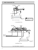
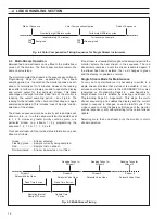
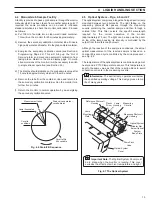
The sample enters the constant head unit situated at the
bottom of the instrument case – see Fig. 4.2A for single stream
and Fig. 4.2B for multi-stream. The constant head units are
fitted with an 'Out of Sample' switch. This switch is used by the
microprocessor, in the appropriate situation, to instigate the
'Out of Service' alarm and energize the emergency sample
valve, if fitted. This optional valve introduces sample from an
alternative supply to maintain the monitor operation when the
sample has been lost. This avoids potential problems caused
when the monitor is run without a sample for long periods.
For the multi-stream version, each sample is presented to
individual constant head units each of which is fitted with an
'Out of Sample' switch (see Fig. 4.2B). Solenoid valves, MSV 1
to 6, attached to each constant head unit are then used to
select each stream to be sampled. The emergency sample
valve is energized when all sample streams are lost or de-
selected.
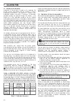
The sample is drawn off from the selected stream by one
channel of the peristaltic pump via the pre-heating coil – see
Fig. 4.2B. The purpose of this coil is to pre-heat the sample
prior to the reaction taking place. Any air bubbles which form in
the sample are removed by the de-gassing block and pumped
to the drain by one channel of the peristaltic pump via valve
SV5 (in the multi-stream version the sample is passed directly
to drain). This is important because bubbles in the sample will
give variable reagent mixing resulting in noisy readings on the
display.
The reagent solution, delivered via one channel of the pump is
then added to the sample before entering the dynamic mixer
block and then passes through the heated delay coil where the
reaction takes place. The resultant solution is then presented
to the measuring cuvette via a solenoid valve SV4 (in the multi-
stream version the solution is passed directly to the cuvette).
Information. The dynamic mixer consists of a
small stirrer situated in a chamber in the mixer block and is
magnetically coupled to a small electric motor.
During an AUTO ZERO, solenoid valve SV1 is used to
introduce the primary standard solution. Solenoid valve SV2 is
used to introduce the secondary standard solution.
The sample pre-heater coil and reaction delay coil are
mounted in a single acrylic block. This block is heated using a
small 24 V cartridge heater and controlled using a PT100
temperature sensor. This optimizes the chemical reaction time
and removes the effect of ambient and sample temperature
changes.
The coils are made from PTFE and do not normally require any
maintenance except for the 5-weekly system flush – see
Section 8.2.2.
If the color compensation sequence is initiated, both SV4 and
SV5 valves are energized. The developed solution passes to
drain and is replaced by undeveloped solution (sample without
reagent) which passes to the cuvette via valve SV5.
After a preset number of fill/drain cycles a measurement of
absorbance is made. This is converted to a phosphate reading
which is then subtracted from the reading on developed
solution. The value displayed is then the color compensated
phosphate concentration.
Timing for the color compensation sequence is shown in
Fig. 4.4.
Fig. 4.3 Flow Schematic of Chemical Section
Note. The color
compensation manifold
and valves SV4 and SV5
are not fitted in the multi-
stream version.


